|
|
Rocket Simulator reference manual
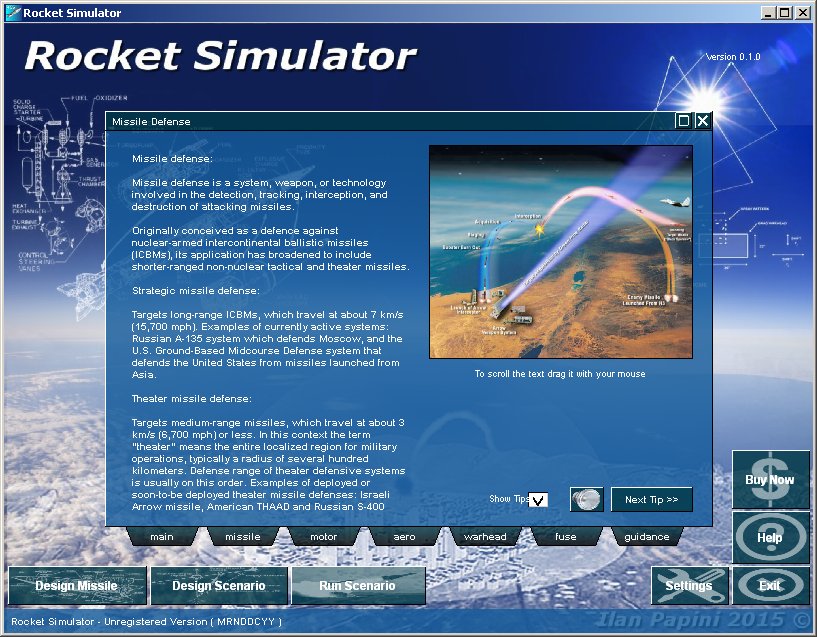
The main screen:Upon start the program will show the main screen, on this screen you can access the following functions:
The Tips System :The Tip System appears in the middile of the main screen, it shows important facts arranged into caterogies. Each tab selects a category, and each time you press it, the next tip from that category is selected, for your convencience you can read out loud the tip by pressing the speaker button on the right side. It is recommended that you view some tips regrading missiles and missile components before attempting to design your own missile. You can turn off the tip system by clearing the show tip checkbox, you can turn it on by checking this checkbox on the graphic options screen. Missile Design:Pressing the Design Missile button on the main screen will show the Design Missile screen, this screen allows you to:
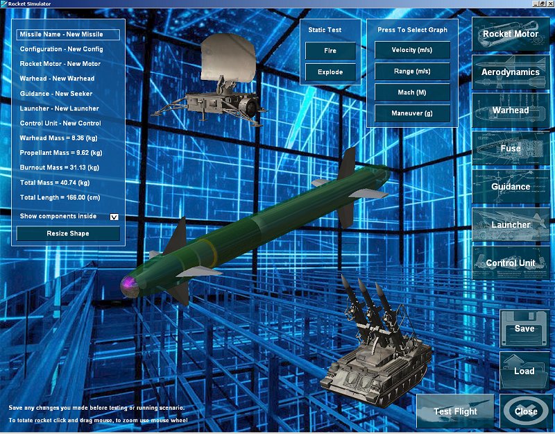
A missile in Rocket Simulator is composed of:
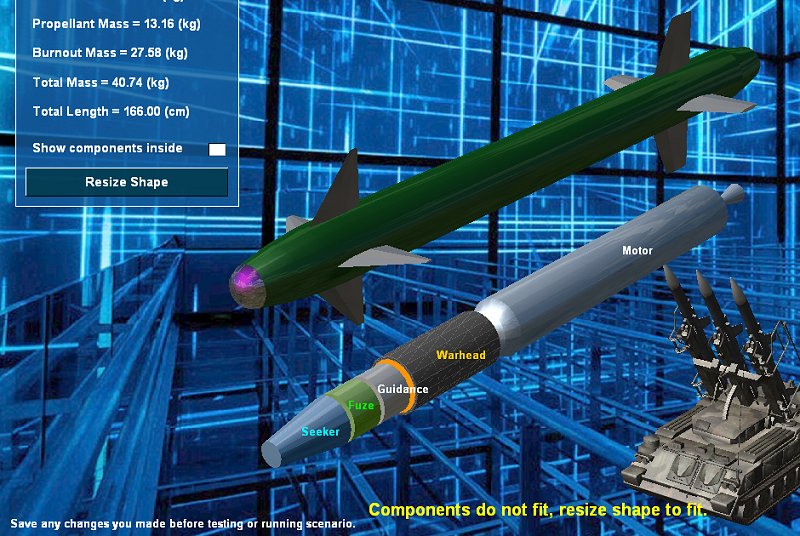
Each of these components can be designed by pressing the relevant button on the missile screen. Once each component is selected from the component screens, it will show in the missile screen. To save or load a missile press the save and load buttons on the right, this will save the missile and all its components as well. The total mass of the missile with and without propellant shows on the left part of the missile screen, also the components themselves can be seen through the missile case in the middle of the missile screen. To zoom the missile view use the mouse wheel, to rotate use the left mouse button. If the components do not fit inside the missile shape you designed, they will be shown outside the shape and a yellow message will be seen, you can quickly fix that by pressing Resize Shape, or you can fix the offending component and then return to the missile screen. You can also press resize shape when the components do fit to make the shap fit them as tightly as possible.
Making a static test:To intercept fast moving targets your missile has to be fast itself, how can you tell how fast the missile will be when its motor is fired, how long will it fly and how far - for this purpose the static test fire was made. The static test assumes the missile flies at sea level and maintains straight and level flight, the thrust of the motor is used to accelerate the missile and fight drag as the missile accelerates. The missile's speed, distance and maneuverability is shown on the graphs that appear on the lower part of the screen, the test is terminated when the missile cannot maneuver more than 4g and it's motor is off. The following graphs can be selected to view the flight data collected:
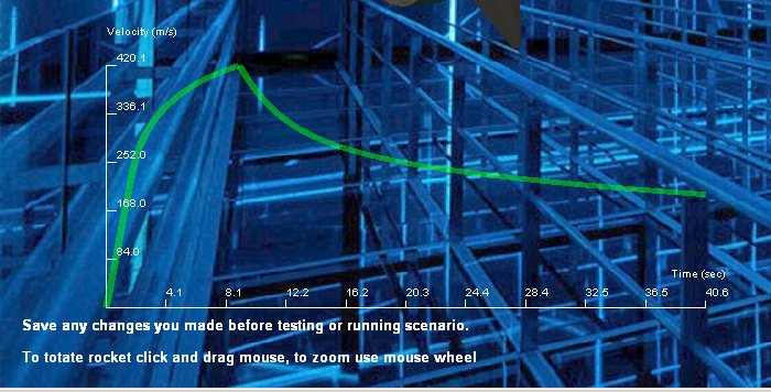
A typical missile with boost and sustain motor will exhibit a velocity graph like the one below, a well design sustain motor will maintain the high speed acheived during the bust stage for as long as possible, making the missile reach long distances and be as maneuverable as possible. The results of the static test can be used to improve the motor, and the missile aerodynamics to fit the purpose you wish it to have, for example to intercept a target moving at Mach 2 the missile itself has to fly at Mach 2 or better, to intercept a target at 10 km from the launcher the missile has to be maneuverable when flying at this range and so on. After satisfactory results has been reached in a static test, you can press the Test Flight button and see how your missile will intercept an actual target in flight.
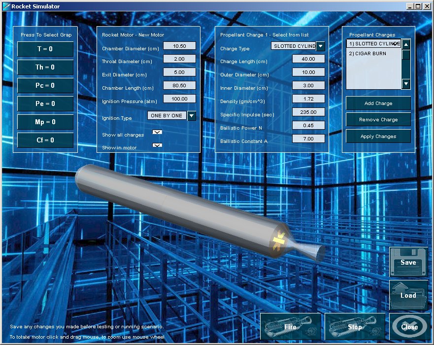
Rocket Motor Design:Press the Rocket Motor button on the Missile screen to see the Rocket Motor Design screen: This screen shows the rocket motor with propellant charges inside, the case is slightly transparent when charges inside so you can see how they fit. On the right side of the screen you see the list of charges and their types, here you can add or remove charges and also apply changes to the rocket motor after you have edited any of the values on the screen. Each charge you select is seen on the second panel to the left, and here you can change its dimensions, type and chemical properties. The specific impulse of the propellant determines how much thrust it will generate per unit weight, while the ballistic constants of it determine how fast it will burn under pressure, to learn about Isp and Burning Rate read the Motor section of the Tips system. The second panel to the left shows the dimensions of the rocket motor and the exaust nozzle, the diameter of the throat of the nozzle has a profound effect upon the pressure developed in the motor burning chamber, and on the burning rate of the propellant, the smaller it is the higher the pressure. The ignition pressure is required to make good use of the propellent to generate thrust, if ignition pressure is high the propellant generates high thrust without delay. Normally charges ignite one by one, when booster charge is ignited first and sustain charge later, you can control this by setting the order of charges you add, and also by setting ignition type. Rocket motors do not operate normally a pressures much above 100 atm, and at sustain even as low as 20 atm, this is because high pressure requires thick walls on the chamber and heavy weight for the engine, so the pressure is always a compromise between engine performance and overall weight. The dimensions of the rocket motor are tightly related to the dimensions of the solid fuel charges, if the charges do not fit, the program will resize the motor case to fit, also if the charges are not filling the entire case you can make the case smaller by sliding the diameter or length and the program will make it as tight as possible.
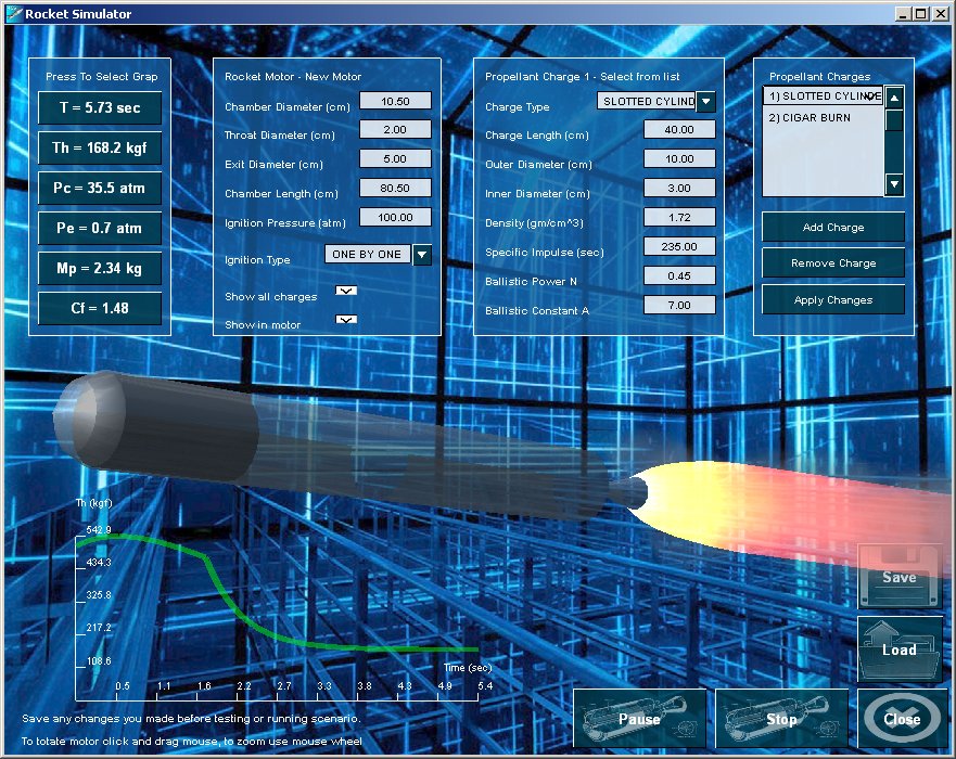
Rocket Motor Static Test:To see how the motor you designed function you should run a statis test fire of it, to do so press the Fire button at the lower right side of the screen. This will ignite the motor and show you the progress of all its important paramters:
To select any of these graphs press the appropreate button on the panel on the left side of the screen. While the motor is burning you may rotate and zoom, and also examine the charges inside and outside of the motor. To see the effect of the thrust curve on missile speed run a static test on the missile design screen.
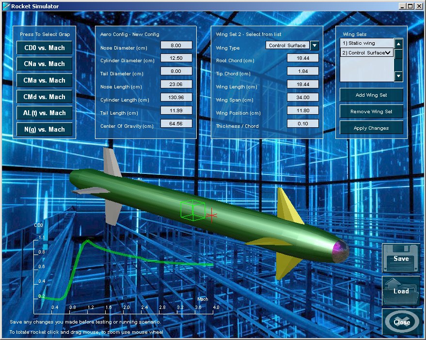
For further reading see: http://www.nakka-rocketry.net/th_grain.html http://www.nakka-rocketry.net/th_nozz.html http://www.nakka-rocketry.net/th_thrst.html http://www.nakka-rocketry.net/th_imp.html http://www.nakka-rocketry.net/th_pres.html Aerodynamic Design :Press the Aerodynamics button on the missile design screen to show the Aerodynamic design screen, this screen allows you to design a missile shape, design its wing sets, select which one controls the missile, and calculate aerodynamic coefficients for this shape. The aerodynamic coefficients determine how much drag the missile has in the various speeds of its flight, its speed, its range, how much maneuverability it has and its stability while manevering. The better the aerodynamics the more capable your missile will be and the faster it will become. As you apply each change to the shape, a new set of aerodynamic coefficients is clalculate for the entire speed domain expect during missile's flight, these coefficients are displayed in the graphs at the lower part of the screen. The following graphs can be presented by pressing the relevant button on the left side panel:
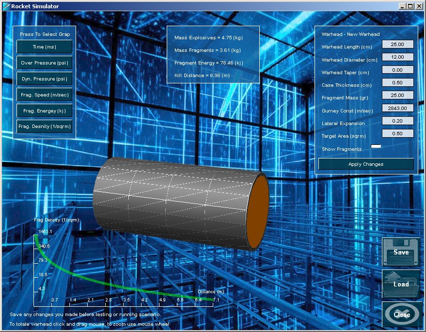
To change the missile's shape use the panel on the left, there you can input the dimensions of the nose, body and tail. Also you can set the position of the center of gravity, which will effect the missile's maneuverability and stability. To change the properies of each wing set use the second panel from the right, you can also move the wing position, and thus control the lift produced by the missile, the trimmed angle of attack it will have and its ability to maneuver at a specified control deflection angle. To add or remove wing sets use the paenl on the right, and also use it to apply any pending changes you have made. Remeber to save your work before exiting this screen so you will not lose the changes you have made. Warhead Design :Press the Warhead button on the missile design screen to show the warhead design screen, on this screen you can design a fragmentation warhead, see its lethality range, and adjust its dimensions to acheive the kill radius you want it to have. The warhead diemsions are adjustable on the left side panel of this screen, the warhead is assumed to be a cylindrical shape of high explosive, surrounded by a metal case which breaks evenly into fragments. Since the damage from fragments is usually the one responsible for killing the target, the adjustment of target area and fragment mass determines the killing range. The killing range of the warhead is determined by the requirement that at least two fragments hit the target area, the number of fragments is determined by the weight of the metal case divided by fragment weight, and fragments are dispersed in a uniform cilyndrical shape around the warhead. The total mass of the explosive, the total mass of the metal case, the energy of the fragment and the killing distance of the warhead against the target area specified are calculated and presented on the panel at the middle of the screen. To see the shape of dispersion and count of fragments being dispersed enable the Show Fragments check box.
After each change you make press Apply Changes to calculate warhead performance, these are shown on the graph area on the bottom of the screen. The following graphs are available for warhead performace:
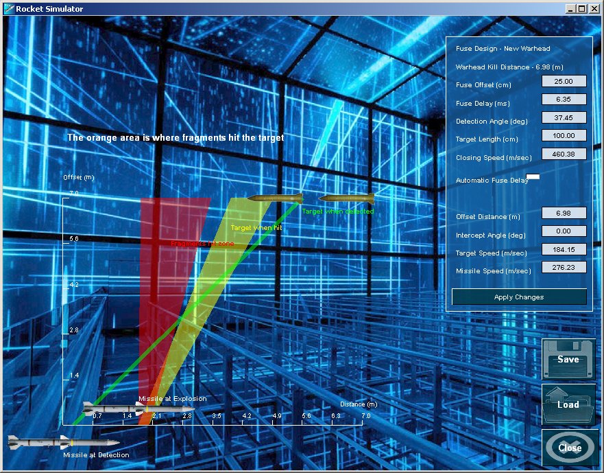
Although the program does not check the damage criteria upon the target, it is recommended that the fragment has enough energy to damage the target, for penetrating and exploding target warheads, a minimum of 80 kj is required, so you must aim your design at this number. To adjust fragmentation energy you can adjust the mass of fragment, and also adjust the ratio between weight of exposive material and weight of the metal shell, the higher this ratio will be the closer the speed of the fragment will be to the speed of expanding gasses thereby acheiving maximum speed and energy. For further reading see: http://fas.org/man/dod-101/navy/docs/es310/warheads/Warheads.htm http://fas.org/man/dod-101/navy/docs/es310/dam_crit/dam_crit.htm Fuse Design :The fuse in Rocket Simulator is an electro optical proximity fuse, which fires a beam ahead of missile in an angle to missile axis, this allows the target to be detected will before it passes over the missile. In addition, a delay between time of detection and time of explosion can be set, although a few milliseconds this delay is very important, so that the fragments narrow beam hits the target exactly as it passes over the missile. It is also assumed that the fusing system can measure the closing speed between target and missile and adjust its fuse delay accordingly, this enables the missile to intercet targets at a wide range of closing speeds and successfully kill them with fragments from the its warhead. You can adjust the fusing system of your missile and inspect various intercept speeds and angles using the Fuse Design screen, press the Fuse button on the missile design screen to see the following screen:
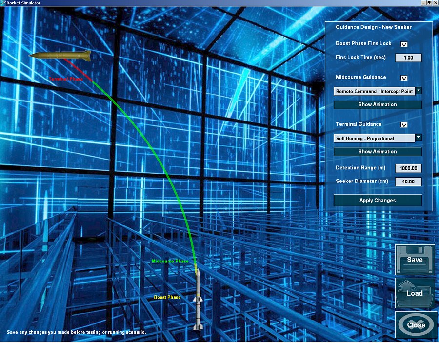
The fuse is directly linked to the warhead of your missile, it uses its killing distance, fragment speed, expansion ratio and axial length for determining the fragmentation zone that you see painted in red on this screen. For this reason fuse and warhead are always saved together, so when you save a fuse you also save a warhead and vise versa. How the fuse works:To understand the function of the fusing screen turn off the Automatic Fuse Delay, now you can see the effect of closing speed, missile speed and target speed upon the zone of tagret position and fragment position at the moment of impact. In this image above, you see on the horizontal axis the position of your missile at the moment of target detection ( at the origin ) and at the moment of warhead detonation, since that moment the fragments travel perpendicular to the missile's flight path at the speeds detemined by the warhead. Adjust the missile speed only using the panel on the right side of the screen, and see how the fragmentation zone gets shifted forwards, this is due to the addition of missile's axial speed to the normal speed of the fragments ( perpendicular to missile's axis ). Also, if there is a fuse delay, the red zone is shifted forwards as the fuse delay multiplied by missile speed gives distance travelled by missile from moment of detection to moment of exploding the warhead. Now try to change only the fuse delay to better understand this shift, as you increase the fuse delay the red zone gets shifted forward towards the target zone painted in yellow. You can also adjust the target speed alone, and see how the yellow zone gets shifted back towards the missile, this is because the target speed multiplied by fuse delay gives distance travelled by the target towards the missile. The reason the fuze beam is tilted forwards, is to provide extra time for the fuse to detect the target and react, and for the fragments to impact the target. When the closing speed is low this is not a problem, since the framents travel much faster than the target, however for fast moving tagrets you may need all the time you can get to make the fragments hit the target, and this can only be acheived by giving the missile an early warning of the coming target. Now, adjust the detection angle only, and see how it shifts the entire target zone forwards, and how it has the same effect as decreasing the fuse delay. When discussing the fuse, the factor we care about is actually the closing speed, since the fuse only senses closing speed, and only the closing speeds effect the delay needed for fragments to hit. Normally fusing systems can detect closing speeds as well as detection range, this detection takes less than a millisecond and during that time a fusing delay can be calculated to make the probability of hit much greater, this function is enabled by selecting automatic fuse delay. For fusing systems that are less advanced, this option can be turned off and you can see which closing speeds result in target hits and which do not. Turn on this option, and see how the time delay alone can make the fragments area overlapp the target area, this appears as an orange zone ( red zone overlapps the yellow zone). Now try to adjust the closing speed alone and see what a wide range of speeds you can cover using auotmatic fuse delay. When closing speeds become very high, even time delay of zero cannot make the fragments hit the target, for this case you can adjust the detection angle forwards, and buy your fuse extra time. You can also adjust the intercept angle and target offset to explore different engagement scenarios, as you can see the fusing system still works using the automatic fuse delay. Understanding this function is a key factor in understanding why the Iron Dome is so effective against a wide variety of targets and why intercepts that seem to have strange intercept angles still result in successful kills of the target. For further reading see: http://fas.org/man/dod-101/navy/docs/fun/part14.htm Guidance Design:A typical missile system may have three phases of flight, boost, midcourse and therminal, during each of these phases the guidance method may be different or non existant. In order to select the modes you wish to have for your missile system, press the Guidance button on the missile design form, the following screen will show. On the right side you see a panel where you can select the phases you wish to enable, to enable all of them check all the three check boxes. The characteristic of the boost phase is that the missile flies in a ballistic path, its fins are locked and no guidance is made. This allows the missile to accelerate to maneuvering speed without losing stability or speed. You can use the static test in the missile design screen to see how many seconds are needed for the missile to accelerate to maneuvering speeds and set this time in the fins lock time input box. During the midcourse stage the missile is normally too far away to detect the target by itself, so it uses some command guidance from its launcher or control unit, there are usually two types available, line of sight ( as in most anti tank missiles ) and intercept point ( where the launcher calculates projected intercept point and guids the missile toward that point). Select the method you prefer and press the animation button to help you understand the drawbacks and andantages of the mode you choose. The size of the seeker will normally dictate its detection range, the larger it is the more sensitive it will be. Set the desired detection range for the terminal phase, and then apply changes, if the result is a diamter larger than the diamter of your missile adjust the diamter and apply changes to get the actual detection range you can acheive. Then select type of terminal guidance and see the animation to understand better how it behaves, missiles that have terminal guidance usually use proportional guidance at this stage.
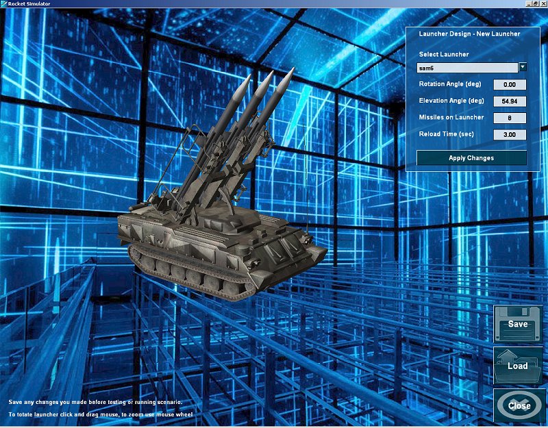
For further reading see: http://fas.org/man/dod-101/navy/docs/fun/part15.htm https://en.wikipedia.org/wiki/Missile_guidance http://www.okieboat.com/History%20guidance%20and%20homing.html Launcher and Control Unit:Press the Launcher button to see the Launcher selection screen, this screen allows you to select the laucher shape from a list of existing launchers, and also the properties of the launcher itself. The launcher shape you select does not necessarily fit the shape and size of your missile, it is only for graphic purposes. Use the elevation angle to select at which angle your missiles will be launched, usually you would want a high angle to handle high incoming threats. The two factors which determine the effectiveness of your missile system against multiple threats are the number of missiles on launcher and the time it takes to reload them. During the last conflicts in which the Iron Dome took part, the system had to defend sgainst multiple incoming rockets fired at once, it did so with flying success due to the clever distribution of missiles and engagements between lauchers and command units. You can try to set different values here and check the same scenario against your missile system and see the results of longer reload time, or of less missiles on the laucher.
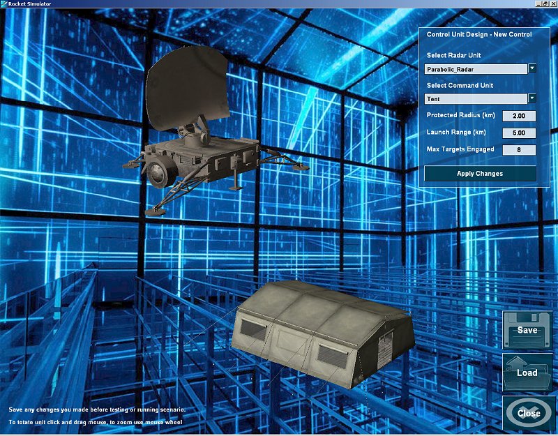
Press the Control button on the missile design screen to see the Control selection screen, this screen allows you to select the shape of control and command unit from a list of existing shapes, and also the properties of the control unit itself. The Radar and Command Unit shapes you select do not influence the performance of your missile, they are only for graphic purposes. The Command Unit will launch missiles at incoming targets when the projected course of these targets falls inside the protected radius around the control unit, and when the range of the incoming target is below the launch range. Use the launch range try to make the intercept of targets as far away from the protexted area as possible, if targets are intercepted inside the protected range, debris from these targets still fall inside your protected eange and will cause damage. Use the static test of your missile to determine the maximum launch range you can set, keep in mind that the targets are also moving towards the control unit, and so the lauch range can be larger than the range of the missile itself as measured in a static test fire. The Protected Radius of your system has to cover the area ( city ) that you wish to protect, so increasing both this area and the lauch range will maximize the effectiveness of your missile system.
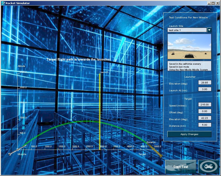
Making a Test Flight:After designing your missile and your launcher and control, it is time to test it against a real target, for this reason you need to make a flight test. Press the Test Flight button on the missile design screen to show the Test Flight screen. Here you can test your missile system against a target launched at the distance, speed, elevation and offset of your choice, and test the behavior of your missile system as a whole. In the next section we will describe the exact data you can extract during a test flight and see how to adjust the test data until your missile system has reached its maximum effectiveness against the targets you want to intercept. At the upper right corner of the screen you see a list of launch sites, you can select where to conduct your test from this list, the list can contain locations from any of the scenery areas you have installed in your program. Below the location list, you see the launcher settings, here you can select elevation angle and distance at which to launch missile against an incoming target. The launch distance can be adjusted and tested until the missile has reached its maximum useful range, then you can set the launch range at your control unit screen and save the settings. Also the angle of elevation can be tested and when you are pleased with the results, you can save this angle into your launcher screen and save these settings. The target settings are the most important elements of the flight test, here you can adjust the elevation, speed, offset and launch distance of your target. On the graph you see, the actual trajectory appears and you can adjust the target angle and speed to match the distance you want it to reach. The yellow marker at the middile shows the launch range of your missile, during the test you can let the system fire automatically when target has reached this range, or you can fire a missile manually and see if it intercepts the target or not. The offset angle of your target will make it aim to the side of your missile system, and can be used to see the effectiveness of your system in protecting a larger area around it.
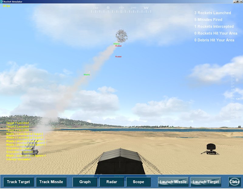
When you are ready to make the actual test press the Start Test button. The Test Mode:The test mode begins as soon as the start test button is pressed or when a situation that was saved in test mode is loaded. The test mode has the following charactristics that distinguish it from other operating modes of the program:
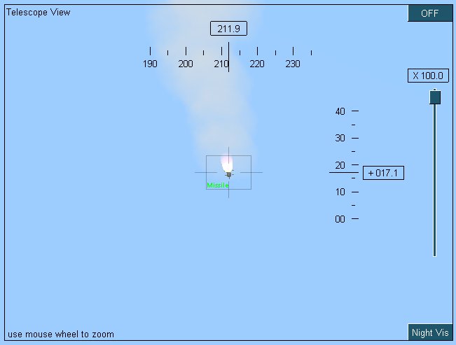
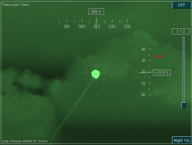
To launch a target press the "Launch Target" button on the Test Bar, then press Track Target to see the target through a telescope and track its trajectory. To launch a missile press the "Launch Missile" button on the Test Bar, then press Track Missile to see the missile through a telescope and track its trajectory. Each time you press the track button a different target is tracked, to release track press the track once more, or press F2. During the flight of a target or a missile you can get the actual graph of flight data by pressing the Graph button. Also you can see the scope and radar by pressing these buttons on the test bar. See below for more information about the Graph, Radar, Scope and Map tools. The Telescope:The Telescope is useful when you wish to zoom in on targets or missiles, when you wish to measure elevation and azimuth, and when you wish to use night vision to see the scene at night. To see the Telescope press T or use the top bar icon or press the Scpe button in test mode. To zoom in and out use the mouse wheel, or drag the slider on the right side.
To use the night vision press the Night Vis button on the lower right side.
To turn the telescope off press the OFF button or press T. The Graph:During the test mode only you can see a graph of missile or target flight data, to see this graph press G or press the Graph button on the Test Bar at the bottom. When a target is in flight the graph will show the data for this target, when a missile is launched the graph will show flight data for this missile. You can select between the following graph types:
Press the buttons on the right to select these graphs. Use the data you see on this graph to adjust the range at which you launch your missile, or adjust the missile itself to operate better at the range you wish to intercept targets.
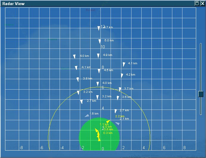
The Radar:The best way to explore the performance of your missile system is by using the Radar, this view show clearly the targets and missiles fired relative to your missile control unit. To show the Radar press R or use the Radar button on upper bar or lower test bar, the following view will appear. The view is aligned toward your point of view, to rotate your point of view drag your right mouse button on screen left or right. To zoom in and out use the mouse wheel, or drag the vertical slider on the right. The green circle represents your control unit position, and the protected radius around it, the yellow arc represents the launch range, any target entering this zone is fired upon. Targets are marked as white triangles, missiles are marked as yellow triangles, and debris marked as faded white triangles.
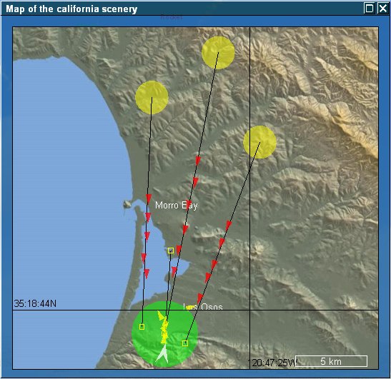
The Map:The Map view also provides a good way to explore the situation, in addition to the view of missiles and targets it also provides the positions of these in relation to your scenery and populated areas in it. Press M or the Map button on the upper bar to show the map, the following view appears. To zoom the map in or out use the mouse wheel, to pan the map drag upon the map in all directions. The titles on the map represent populated area, the yellow circles represent the location of rocket launchers, the green circle represent the location of missile system and its size is the protected radius around it. The black lines from rocket launchers represent the project flight path of the rockets, and the yellow rectangles are the projected impact points of these rockets. The rockets in flight are shown as red triangles, the missiles are shown as yellow triangles. The map is always facing north, the scale in kilometers is shown on the lower right corner.
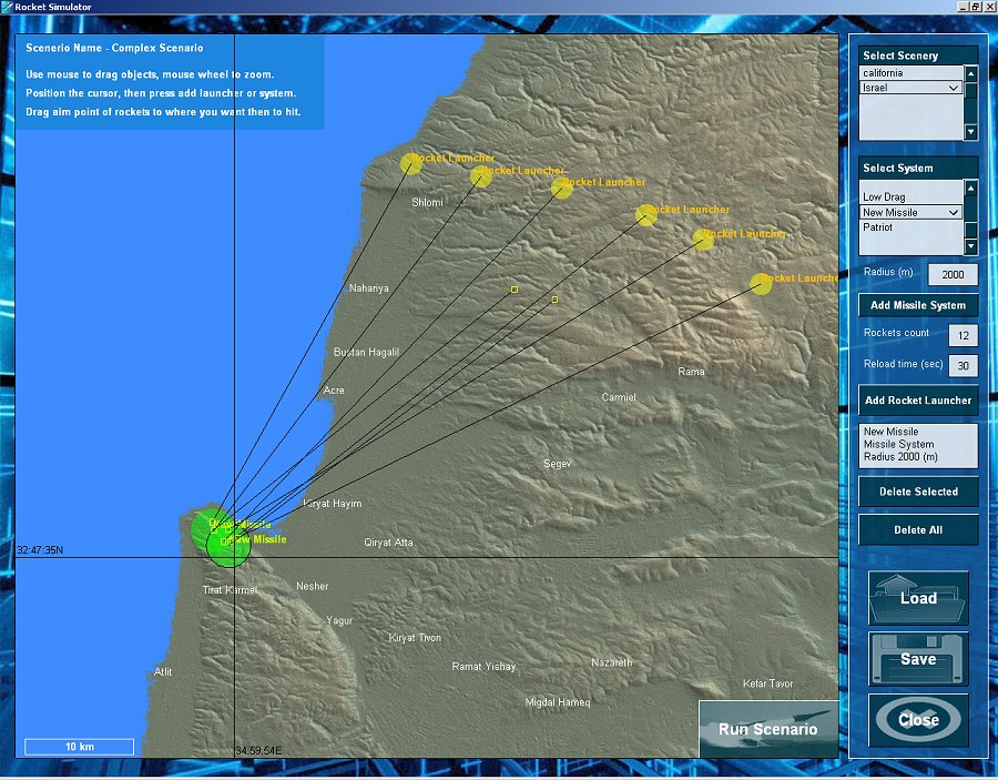
Scenario Design:The essence of Rocket Simulator is it's ability to design and simulate a scenario. A scenario is a situation in which one or more missile system defends an area against one or more rocket launchers. During a scenario you can only watch the events unfold and hope your missile systems are designed well enough to defend the area of interest. The scenario begins with rockets being fired at your areas of interest, and your missile systems detect, track and intercept these rockets, the scenario ends when there are no longer rockets or missiles in the air, and a score is given according to the amount of rockets and debris that hit the defended areas. The Scenario Design screen below is used to define the locations of rocket launchers and missile systems in your scenario, and set some properties for them, such as rocket impact points, rockets count, launch interval, and orientation of missile systems. Press the Design Scenario button on the main screen to show the following screen. First you need to select a scenery for your scenario, to do so select one from the list on the upper right corner of the screen. Then click the mouse on the map, zoom it using the mouse wheel and pan it to the place where you wish to position your missile systems. To add a rocket launcher:Define the propeties of the rocket launcher, define number of rockets on launcher, define the interval between rocket launches. Press the left mouse button on the map where you wish to add the rocket launcher, then press Add Rocket Launcher. Drag the yellow rectangle to where you want the impact point to be. Drag the yellow circle where you want the rocket launcher to be. You can also set these properties after you have added the rocket laucher, but you need to press enter in the textbox of these paramters to make them apply to the selected launcher. To add a missile system:Select the type of the missile system from the missile systems list. Press the left mouse button on the map where you wish to add the missile system, then press Add Missile System. Drag the yellow rectangle to indicate the orientation of the missile system, the position itself is not important. Drag the green circle where you want the missile system to be, the green circle indicates the size of the protected zone around it. You can also set these properties after you have added the missile system, for this you need to select the system, then select its type from the list on the right.
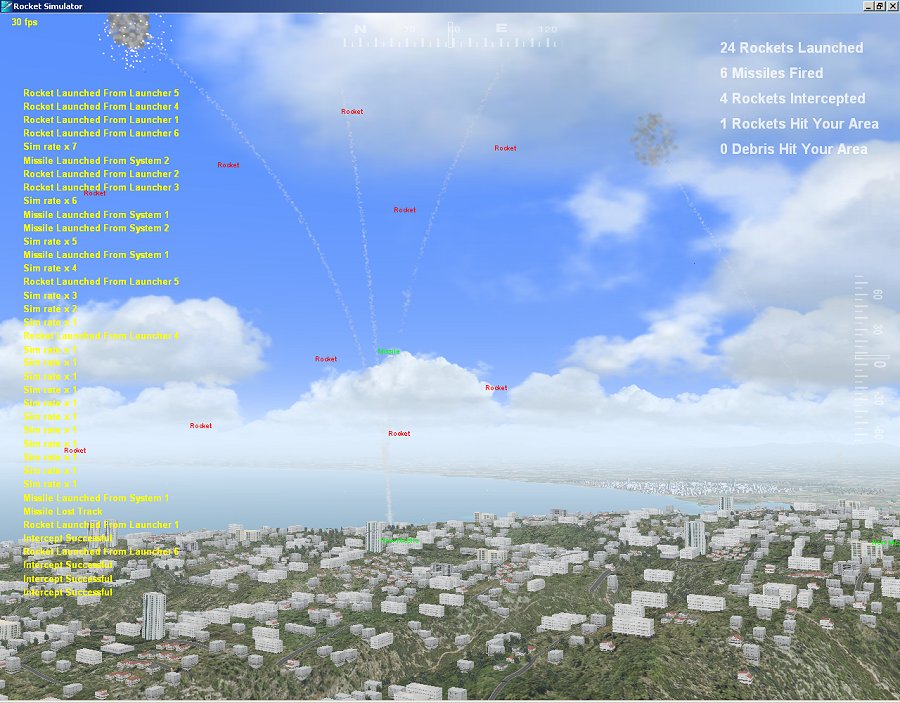
You can save the scenario for later use, load it at any time and edit it, or you can run it from the scenario design screen. The Scenario Mode:The essence of Rocket Simulator is it's ability to design and simulate a scenario. A scenario is a situation in which one or more missile system defends an area against one or more rocket launchers. During a scenario you can only watch the events unfold and hope your missile systems are designed well enough to defend the area of interest. The scenario mode begins when you press the Run Scenario button in Scenario Design or when a situation that was saved in scenario mode is loaded. The scenario begins with rockets being fired at your defended area, and your missile systems detect, track and intercept these rockets. The scenario ends when there are no longer rockets or missiles in the air, and a score is given according to the amount of rockets and debris that hit the defended areas. As soon as a missile system detects an incoming threat a siren is sounded, this siren can be turn off quickly using the S button, or using the options or sound dialog. During the scenario you have no control over when targets or missiles are launched, you can watch from any point of view, you can use Radar, Map, Telescope to see how missiles and tagrets behave, and you get a score at the end showing the success rate of your missile defence. A scenario can run by day or night, you can control the weather and time of day anytime you want by pressing W or O.
At the top of the scenario screen you see a summary of the rockets beeing shot and intercepted, your score is derived from this summary at the end of the scenario. On the left side you see the verbose display of events, you can turn this off using the options dialog, however this mode helps you understand the events that take place, and in case you missiles do not hit the targets you can see why. Events such as system reloading in x seconds, help you understand why some targets are not intercepted in time, events such as missile lost track, help you understand that missiles are not fast enough to reach your targets. To better enjoy the scenario mode, it is important that you know the basic keys or shortcuts that control your program. Controls and Keys:Rocket Simulator uses the following controls and keys to control the functions you need.
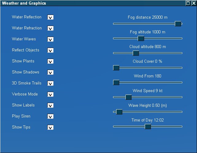
Weather and Settings:To make the program as simple to use as possible, the weather and settings were combined into one screen, press O or W while in test or scenario mode, or use the Settings, Graphics from the main screen to see the Weather and Settings screen. The weather settings appear on the right side of the screen and can all be adjusted while the program runs, changes are made immediately. Weather settings include: Fog distance - visibility of low atmosphere layer. Fog altitude - thickness of low atmosphere layer. Cloud altitude - cloud base elevation. Clound cover - cloud coverage. Wind From - direction from which wind is blowing. Wind speed - speed on wind. Wave Height - height of waves in sea ( when Water Waves are enabled ). Time of Day - the hour and time of day, date is not taken into account. Graphic settings include: Water Reflections - enabled reflections on the water surface. Water Refractions - enables the sea bottom to be seen through the water. Water Waves - enables waves to be seen on the water when close to the surface. Reflect Objects - enables reflection of objects on water when close to the surface. Show Plants - enables plants and grass to be seen on land. Show Shadows - enables shadows on land, objects and plants. 3D Smoke Trails - enables 3D smoke for missiles and rockets, may slow down the rendering when multiple missiles are in the air. Verbose Mode - prints out many notifications which help you understand what is going on and why. Play Siren - plays a siren when threats are detected, siren is stopped when no threats or missiles are in the air. Show Tips - show the tips system on the main screen by default, refreshing the tips when you get back to main screen.
|