![]()
Vehicle Simulator was created by Ilan Papini first version released in October
2008.
Vehicle Simulator is based upon two older programs developed by Ilan - Micro
Flight and Virtual Sailor,
the first was a full fledged flight simulator and the second being a full
fledged marine simulator.
During the years of their existence the power of the personal computer and 3D
graphics increased so much that it became possible to combine the best of both
worlds into one program containing :
Vehicle Simulator is a complete rewrite and complete conceptual redesign
based upon the two programs above, resulting in a much denser scenery than
before, excellent physical simulation, and scalable design allowing it to grow
and contain more types of vehicles and objects.
The greatest benefit of all is offering a single platform for content
development for both types of applications, allowing flight simulation to happen
over the same scenery as naval simulations, and for planes to land on vehicles and
more.
Vehicle Simulator includes an intuitive and simple scenery design inside the 3D
environment, making it much simpler for users to create and share content than
before.
The program uses fully documented formats for creating scenery, vehicles and animals, users are encouraged to get a hands on experience designing and making add-ons and to share them with others.
Advanced add-ons can be created using DLLs for instrument panels, animals and scenery objects, source code for such DLLs is given as part of the program to encourage advanced users to develop high quality content for the program.
The program is fully compatible with scenery, boats and planes made for Virtual Sailor or Micro Flight, after installing these add-ons the program imports them automatically and creates the new vehicle paramters needed for them to run.
Vehicles can be edited and created inside the program and accurate physical properties can be set for them and tested in fligth or sail, making the program an excellet tool for learing the phyisical properties of these vehicles and their design.
Documentation and tools for designing scenery, vehicles and animals can be found on the websites of Vehicle Simulator.
www.hangsim.com/vsf
www.qualitysimulations.com/vsf
Vehicle Simulator was designed to run on the average gaming machine specs
available for 2008, however it can be adjusted to run on machines with less
performance.
Vehicle Simulator is built to use DirectX9 with vertex and pixel shaders 2.0 and
volumetric textures.
It is
essential that your computer has a video card which is compatible with DirectX9.
Minimum Requirements
CPU: Intel Pentium 4 2.0 GHz, Intel Core 2.0 GHz, AMD Athlon 2000 or better
RAM: 1GB
Video Card: NVIDIA GeForce 6800 GT, ATI Radeon 9800 Pro or better
VRAM: 128MB of Graphics Memory
Sound Card: DirectX 9.0c Compatible
OS: Microsoft Windows XP or Vista or Windows 7
DirectX: DX9.0c or DX10
Vehicle Simulator has several websites in which you can download more vehicles and scenery, and also get more information about creating these add-ons, these sites are the main sites and from them you can access the partner sites which offer much more content:
www.hangsim.com/vsf
www.qualitysimulations.com/vsf
To install vehicles and scenery follow this procedure:
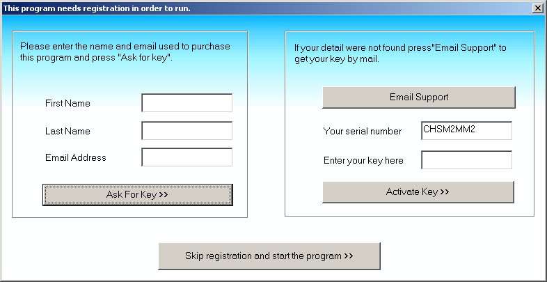
When you run Vehicle Simulator for the first time you will see one or more of these input screens:
This screen is required for the program to identify your registration, if you have purchased your program online please enter the first and last name you used for purchasing and the email you received the program to and press Ask for key.
If your registration is found your key will be sent to you by email after
pressing this button.
After receiving the key, run the program again and enter the key into the
textbox below, then press "Activate Key" button.
If you do not have a key press "Skip registration and run the
program", this will run the program in demo mode until you enter the key for it.
Upon start the program will show the opening screen, this screen can be used to select the situation you want to use or adjust any of the program's settings.
When you press "Load" the following screen will appear, this screen is also accessible from inside the main menu of the program.
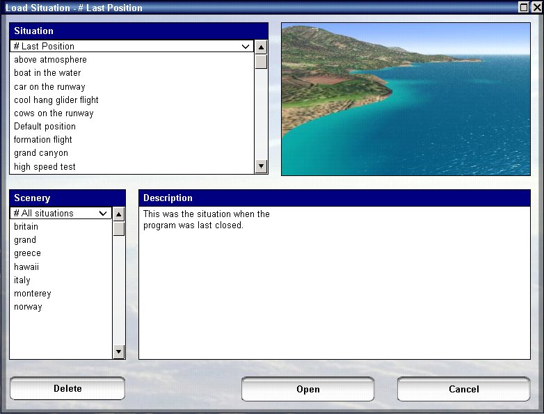
On the left side of the screen you select the scenery from which you want the
situation file to begin, on the right you see a list of available situations for this
scenery.
After you select situation from the right side, you see the screenshot appear above, and the description below.
When you are ready to start the selected situation press "Start".
When you press "Settings" the video dialog will appear, this screen has several tabs as well which select the settings you can adjust for the program, these include video, sound and joystick.
Press the "Video" tab to see the video settings, this will show the following screen:
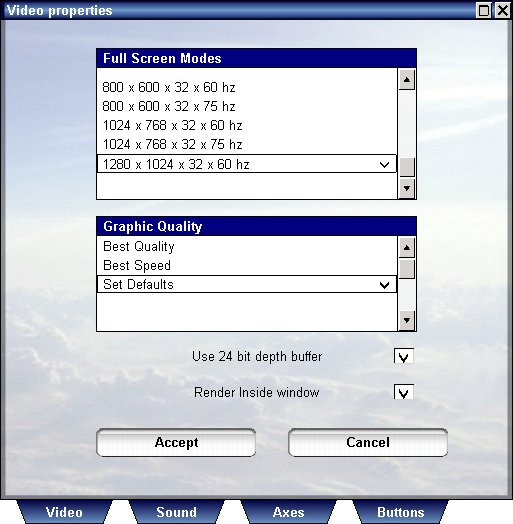
In this screen you can select whether you want to use the program in full screen mode or window mode, and set the size and refresh rate of the full screen mode.
Using full screen modes allows the program to run faster when using lower resolutions as less computations for pixel shaders are performed.
The benefit of using a windowed mode is that it allows the program to be
minimized and run minimized, and also allows resizing of the program's window to
suit your needs.
The top of this dialog shows available screen modes, to select one of them,
you need to clear the option "Render inside window" and press
"Accept".
The "Use 24 bit depth buffer" allows you to render the view with less artifacts near the horizon, these artifacts are sometimes created when the distance of objects from camera is almost identical and the video card cannot tell which is closer, this results in flickering of some polygons near the horizon, this mode is also necessary for showing proper shadows in some cases.
The Graphic Quality settings allow you to adjust the general graphic quality
of the program before you open any situation, and also during an open situation.
If your computer exhibits low frame rates in situations close to the ground or
others, you may select "Best Speed" to test how frame rates can be
when all the high level features such as generated objects and vegetation are
turned off.
If your computer does not meet the minimal specifications or you are experiencing low frame rates open this dialog and select "Best Speed".
Press the "Sound" tab to see the sound settings, this will show the following screen:
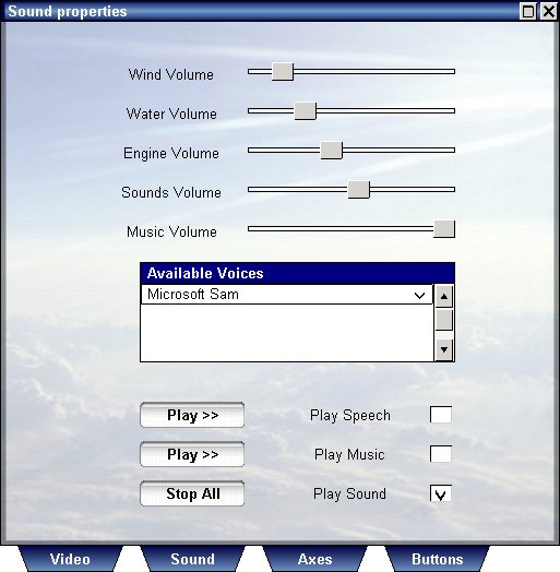
This screen allows you to set the volume for the wind, waves, engine and
other sounds, to enable music and speech, and select the voice of the
speaker to use.
The program uses the built in Microsoft text to speech engine, you can customize
speakers by downloading additional speaker voices from the internet.
To play speech inside the program, select "Play speech when
required" and select the voice of the speaker you wish to set from the list
of speakers above.
To play music inside the program enable the "Play music when
required", this will play an opening music on the main screen of the
program and also play music on situation start.
You can customize the music you hear during the game, look inside the music directory to add or remove mp3 files.
Press the "Joystick" tab to see the joystick settings, this will show the following screen:
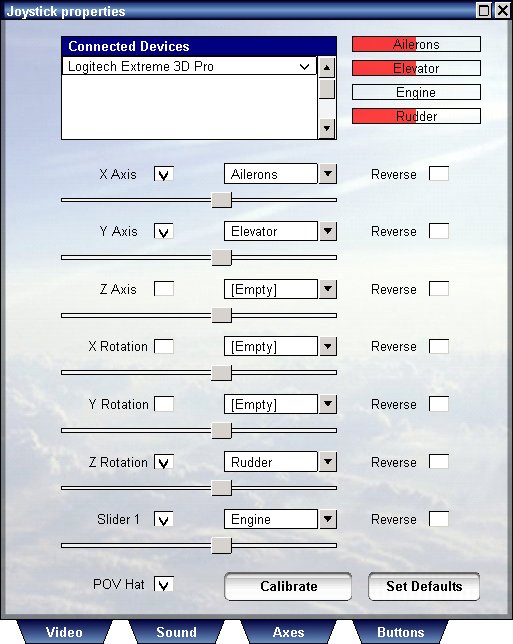
This screen allows you to select axes and sensitivities of joysticks you have attached and assign their inputs for the program.
Vehicle Simulator allows up to 6 joysticks connected simultaneously, for each joystick you see one line on the list that appear on the upper part of the dialog.
To select which axes you want to assign for these
joysticks, select the joystick first from the list above, then assign the actions you wish to
set.
For each joystick the assigned actions are different, selecting
engine for example for joystick number 1 will unselect this option for the other
joysticks on the list.
Each axis you assign will be drawn on the upper right corner so that you can see its function.
When the program starts for the first time it will select the default axes of your joystick according to the settings it detects, to set default axis assignment press "Set Defaults".
Vehicle Simulator also supports POV hats, and also Track-IR with vector expansion, when Track-IR is detected you will see an option called "Track-IR appear near the POV hat option box.
For each axis you wish to assign enable the check box near it's name, then select the type of action you wish to assign to it, in addition, you can adjust its sensitivity or reverse it's action.
To assign buttons for each of these joysticks, press "Buttons", the following dialog will appear:
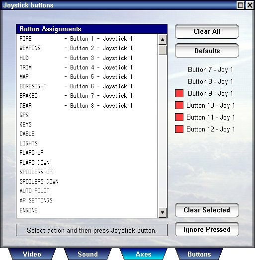
This dialog is much simpler, to assign an action for any button from any joystick you have connected, select the type of action from the list below, and press the button on the joystick, if the button is identified it will appear on the list beside the action you selected and the joystick from which it was read.
When the program starts for the first time it will select the default buttons
of
your joystick according to the setting it detects, if you wish to set this
default selection again press "Defaults".
Some joysticks use buttons for mode selection, when this is the case some
buttons appear pressed without actually pressing them,
To ignore these buttons press "Ignore Selected" and then proceed to
assign buttons normally.
The ignored buttons appear on the right side of the dialog without a red rectangle, the other buttons you press appear with a red triangle.
To clear an assignment or to clear the ignore button list, press "Clear
Selected".
To clear all button assignments press "Clear", to return to the
axes assignment press "Axes".
This option is available only while the situation is loaded, select it from the main menu or press "O" see the graphic settings, these include three subcategories: water ,Land and others.
A good understanding of these settings is essential for using the program to it's maximum potential, please read this section carefully.
Press the "Water" tab to show the water settings, this will show the following screen:
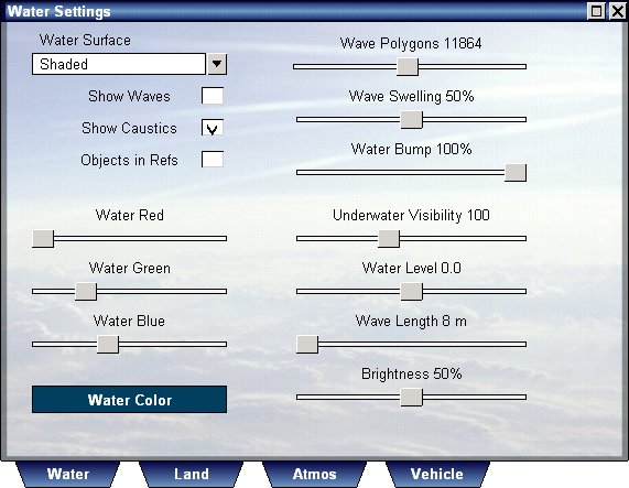
On the upper left corner you will find the sea surface settings, these select how to render the sea and which graphic options to use.
Rendering a realistic looking water can be a very demanding task on your CPU and video card, for some situations it is best not to use waves, but to show ripples only, for example using the program for flight simulation does not require animated water in most cases, but water animation may be required when you fly close to the water or land upon water.
Reflection and refraction require some heavier computations, as they require the program to render the land and objects more than once.
In order to speed up the rendering, water settings are used when altitude is low enough to appreciate them, at higher altitude the water becomes more simple and default to ripples and next to shaded surface very high.
Foam is formed on water when waves are used and wind and wave swelling are large enough, the roughness and wave shape of water surface can be adjusted using the "Wave Swelling" and "Water Bump" sliders.
These are the available sea modes:
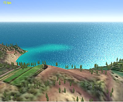
Shaded ( no waves ) :This is the fastest and the default mode of rendering for the sea surface, suitable for flight and general sea visualization. Adjust the wave length and water bump to change the appearance of water in this mode, the tones of water are determined by the depth of bottom and the color of the sea. |
 |
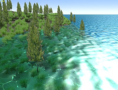
Refraction ( no waves) :One of the best looking water modes, require more processing power to render, to make objects appear in refraction enable "Objects in Refs". To see caustics above and below water enable "Show Caustics". Adjust the wave length and water bump to change the appearance of water in this mode, the color of water is determined by the color of the sea. |
 |
Reflection + Refraction ( no waves ) :This is the most realistic and demanding sea mode, suitable for shallow waters and relatively calm sea. To see caustics above and below water enable "Show Caustics". Adjust the wave length and water bump to change the appearance of water in this mode, the color of water is determined by the color of the sea. |
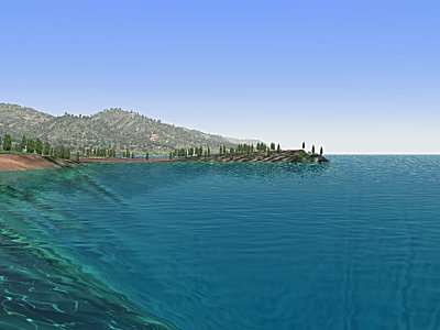 |
Shaded with waves:This mode is best suitable for simulating ships and seaplanes, refraction and reflection can be used as well, but realism is adequate when shaded is used. Adjust the wave length, wave swelling and water bump to change the appearance of water in this mode, the color of water is determined by the color of the sea. |
 |
The view underwater:Using all these sea modes will of course effect the underwater view as well, basically underwater view is dominated by the reflection of underwater view on the surface of the water, so the most realistic views underwater will be the last two modes above, using refraction will also allow you to see a "fish eye" view of above water view. Select "Show Caustics" to enable caustic lighting on the bottom, and also show god rays. |
 |
In addition to setting the sea mode, you can adjust the color of the sea. use the three sliders to adjust the color by red, green and blue.
Wave are rendered more densely close to the camera, depending upon the
number of polygons used for rendering the waves.
You can control the number of these polygons by using the "Wave Polygons"
slider.
Wave swelling controls the shape of the waves, no swelling will make the
waves very smooth, while high swelling will make them choppy and breaking.
Water bump controls the intensity of water ripples, this is the main control for
the sea without waves.
Wave length provides additional control over wave shape, use longer waves to
create long swells, and shorter waves to make ordinary wind driven waves.
The basic wave height is set in the weather dialog.
Water level adjusts the level of water in the entire scenery, water of
different elevation is not possible.
Any water level may be set, slide the slide over and over again until the
desired level is set.
Underwater visibility set the maximal viewing distance underwater.
Show Caustics is used to show caustics on sea bottom and objects, and also to show the god rays emanating from the sun.
The underwater settings, are found in the middle of the water dialog, you can select the type and complexity of the sea bottom you wish to see, and also the properties of the water.
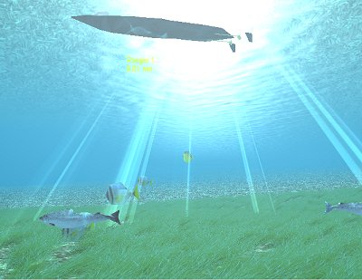
Vehicle Simulator supports underwater scenery, when such scenery exists, the
objects underwater will be shown with caustics as well.
Marine life can be added to make the view more alive, rocks, plants and
particles ( or little bubbles ) can be shown by the program even if not defined
in the scenery itself.
The program creates by default particles, rocks and plants using standard textures read from the scenery, and allows you to adjust their size and density, the five sliders on the right side of this dialog control these settings.
Press the "Land" tab to show the land settings, this will show the following screen:
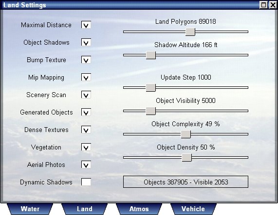
This dialog adjusts the appearance of land and the objects upon it.
Maximal Distance, adjusts the land so that it appears dense even at a great distance from camera, the disadvantage of this is that when you rotate the camera the land has to be calculated again to maintain this high level of detail, turn this option off if you want to fly or rotate your view quickly.
Object Shadows, causes objects to cast shadows, these shadows are seen on vegetation and on dense land textures, if none of these is enabled the shadows will not be seen.
Bump Texture, makes the land textures appear sharper due to pre calculated bump applied on them, this method is faster than applying bump continuously but requires the land to be re calculated when time of day changes by at least two hours.
Mip Mapping, allows the land textures to be reduced in size far from camera while maintaining the same visual appearance.
Scenery Scan, allows the program to check if scenery has changed and load new
one, based upon the geographic coordinates at camera position.
Use this option always unless you wish to navigate away from scenery borders and
prevent the scenery from being unloaded.
Generated Objects, these objects are generated automatically by the program and appear relative to ground texture, see object design for more information about creating and changing these objects, turn this option off if you wish to see a clean scenery with highest possible frame rates.
Dense Textures, these are the textures that appear as you go near the ground, upon these textures shows are drawn and vegetation appears, these textures greatly increase the visual experience close to the ground, however are computationally heavy as they use pixel shaders.
Vegetation, are arrays of plants or trees that are generated by the program and occluded upon objects or roads, greatly increase the visual experience close to the ground, computationally heavy, as they include tens of thousands of elements, turn off when high frame rate close to the ground is required, see object design for more information about creating and customizing vegetation.
Aerial Photos, each scenery can have one or more areas of photorealistic
textures defined, these are defined inside the scenery files, and override the
default land texture and vegetation.
Whenever defined, these photos enhance the realism of the scenery, but can be
turned off to allow the default generated texture to appear instead.
Land Polygons, are the number of polygons rendered for the land, you can increase this number to make land appear more dense far from camera, or turn on "Maximal Distance" at the expense of speed of rendering.
Shadow Altitude, is the altitude at which shadows and dense textures begin to appear, you can adjust this value to make land appear more dense close to the ground.
Object Visibility, is the maximum distance for which user defined objects or generated objects are visible, the greater it is the slower rendering will become.
Object Complexity, controls the density of arrays of all types, vegetation and user defined, increasing will make scenery appear more dense at the expense of rendering speed.
Object Desnsity, controls the amount of automatic objects to be rendered, since the number of these objects can be very big, loading and rendering times may be long, you can reduce these times by reducing the number of objects rendered.
Update Step, controls the distance between object loading points, when distance travelled is greater than update step, the program releases far objects and load new objects, the greater the distance the more you can fly without delays, however this will increase the time required to load objects as more objects need to be updated.
Press the "Other" tab to show the other settings, this will show the following screen:

Show Thermals, this option allows you to see thermals, even ones at a great
distance from the camera.
there is a more sophisticated way to see thermal activity and more, and that is
to see the flow field.
The flow field, is a unique Vehicle Simulator feature which allows you to see the flow field around the camera, points of rising air are visualized as red lines, while sinking air is drawn as blue lines, the length of these lines is proportional to the air speed at this point.
Using this dialog you can show or hide this field, change its density, and
size around camera position.
Interesting atmospheric effects can be see using this filed, like the
doughnut shaped thermal flows, cloud updrafts and micro bursts, ridge
effects and more.
This screen also allows you to adjust current speed and direction, all objects floating on water are subject to this current.
Layered Fog, is one of the most visually pleasing and innovative features in Vehicle Simulator, enable it always if you wish to enjoy a realistic atmospheric view, disable it to make atmosphere simpler with a uniform fog, the altitude at which fog is materializing can be adjusted in the weather dialog, using fog altitude.
Wind Shadows are the effects of wind obstruction between boats usually, when sailing in close proximity of each other, and one boat is upwind of the other, wind may be partially obscured by it, effecting the boat downwind, this option enables this effect and will influence all types of vehicles.
Wind Gusts, enables the turbolence and wind gusts, the actual paramters of wind gust can be found inside the advanced weather options dialog.
CPU idle time, controls how much time you wish the CPU to spend outside of the program, normally to get maximum performance you need to set this time to 0, however you may force the program to give way some of the time and allow other tasks, this slider controls this time and indirectly the CPU load that can be used by the program.
Simulation Step, this is the minimal time step used by the program for each update of its physical simulation, the smaller it is the more stable the calculation will be and the more accurate, however it will also cost more CPU resources, edpecially for multiple vehicles, and multiple collisions and reactions, a typical value for best accuricy will be 5 ms, while for loose accuricy and better speeds, 50 ms is enough.
Press the "Vehicle Options" button to show the vehicle settings, this will show the following screen:
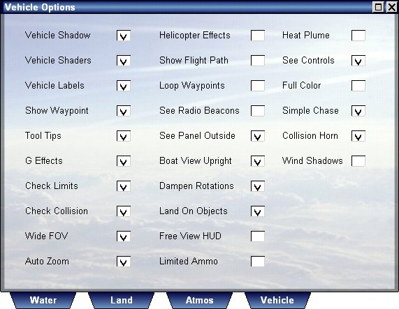
Vehicle Shadow is implemented using several methods, shaders are used for creating soft shadows upon the vehicle itself, inside it, or upon grass and ground at low altitude, high above the ground another method is used, and shadow becomes sharper.
Enable vehicle shadow and vehicle shaders if you wish to see advanced and realistic vehicle view, with reflection, bump maps, and self shadow, however the cost is lower frame rates.


Vehicle Labels, are the small labels that appear on vehicles, these make it easier for you to see where vehicles are and at what distance they are at.
Show Waypoints, this option draw waypoints as rotating 3D objects, and allows you to see them accurately, to increase navigation realism turn this option off.
Tool Tips, are the hints that appear as you press your mouse upon a control or instrument on the panel.
G Effects, are the gray or red screens that appear as you pull your positive or negative g, this imitates the effects felt by pilots pulling positive or negative g and is called blackout and redout respectively.
Check Limits, and Check Collision, these options detect stress and impact on your vehicle and break it when its limits are exceeded.
Wide Fov, this option sets the camera field of view to a normal 45 degree view or a wide 57 degree view, press F7 to toggle this option on/off.
Auto Zoom, tracks your vehicle while tower view is selected, press F6 to toggle this option on/off in tower view.
Helicopter effects, enable this option to make helicopters more realistic to fly, and include effects such as translational lift effect, sink under power and torque, disable this option to make helicopter flight auto coordinated and more enjoyable.
Show Flight Path, use this option to see the path flown by your vehicle in
3D, press Shift P to toggle this path on/off.
Flight path is also visible when you show the replay screen.
Loop Waypoints, use this option to make navigation looping, making your first waypoint active as soon as you reach the last one.
Show Navaids, is a new feature built into Vehicle Simulator, when navigation aids are selected for your vehicle, you can see them visually and learn to navigate by them, these include VOR, ADF, ILS and typically looks like this picture.
See Panel Outside, allows panels of boats or planes to be see when outside of vehicle cabin, however this slows down the rendering a bit.
Boat View Upright, when enabled allows boat view to be aligned with the horison, similar to the tendency of the human head to follow the horizon when the boat pitch and rolls, diabling this option allows better feel of the wave motion but can cause uneasy feeling for the observer.
Dampen Roatations, allows smoother and more predictable motion of boats and other vehicles, but can reduce turning rates, especially when simulation step is large.
Land On Objects, allows the camera and vehicles to detect horizonal object surfaces quickly and not penetrate through them, slow rendering a little and can prevent the camera or vehicle from entering structures such as hangars and buildings.
Free View HUD, when enabled shows the direction of the camera on the HUD, when disabled shows the direction of the vehicle, when working with free view HUD remember that the compass heading is not the direction of your vehicle but the direction of your view.
Limited Ammo, when this option is enabled the amount of cannon shells is limited, the number of stores is limited, and unless you reload will be depleted when fired.

Heat Plume, this option enables heat plume to be seen instead of smoke for jet engines, this option can slow down rendering.
See Controls, this option shows the controls mini panel, on the lower right side of the screen, there you can see the state of elevator, rudder, throttles, and ailerons.
Full Color, this option loads vehicle textures in full color, although smoother to see, it uses more texture memory and might not be suitable for loading very large models.
Simple Chase, when enabled the chase view tracks the vehicle only in yaw and not in pitch, when diabled chase view also tracks in pitch.
Collision Horn, when enabled boats that detect collision course, will sound the horn to warn each other.
Wind Shadows, when enabled will detect wind obstructions between boats and will effect the appearant wind felt on the boat which is downwind of the obstruction.
Press the "Help" tab to see the help options, these include four
items: keys , about, manual and website.
Press the "Keys" tab to show you a list of keys used by the
program, this list is also available inside the program pressing K.
Press the "About" tab to show you short information about this
program including your serial number.
Press the "Manual" tab to show you this help.
Press the "Website" to see the main website of Vehicle Simulator at
www.hangsim.com/vsf
Press "Start" to enter the program and start your selected situation, this will show
you the program main screen.
When you move your mouse to the upper part of the screen the main menu will appear.
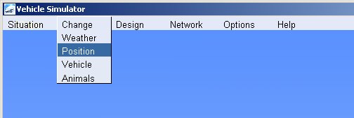
The main menu has access to all functions of the program, these include:
Situation - loading a situation, saving a situation, exit the program.
Change - managing vehicles, changing scenery, changing weather, managing animals.
Design - designing textures, vegetation and objects in your scenery.
Network - shows the net play connectivity dialog, activates the chat window.
Options - Allows you to adjust settings for the video, sound, joystick and the graphics of the program.
Help - Shows you the keys used in the program and the information about this program and your serial number
Vehicle Simulator has three ways of controlling vehicles :
click and drag of the mouse, using the joystick and using the keyboard.
These are the keys used by the program to activate all of these functions:
| Simulation and time: |
| F3 - lower sim rate F4 - increase sim rate F10 - pause simulation Shift + F3 - lower sim rate ( unlimited ) Shift + F4 - increase sim rate ( unlimited ) Shift + M - toggle FPS and application data Escape - pause and show exit |
| Camera controls: |
| PgDn lower camera or vehicle PgUp raise camera or vehicle Z - zoom in X - zoom out Shift + Z - normal FOV Shift + X - normal FOV Shift + V - Viewpoints Shift + T - Telescope Home - move forward End - move back Numkey5 - center view Numkey4 - pan left Numkey6 - pan right Numkey8 - pan up Numkey2 - pan down Numkey9 - move forward Numkey7 - move back Numkey3 - move right Numkey1 - move left Numkey. - move up Numkey0 - move down Control + Space - center view Control + Left - pan left Control + Right - pan right Control + Up - pan up Control + Down - pan down Mouse + Rbutton - pan camera |
| Vehicle selection: |
| Tab - change vehicle Shift + Tab - change view point Control + Tab - change and track F1 - attach to vehicle - cockpit view F2 - chase view - detach from vehicle F5 - toggle tower view F6 - toggle auto zoom ( in tower view ) F7 - toggle wide view ( in cockpit view ) Mouse wheel - zoom ( in cockpit view ) Mouse wheel - change distance ( in chase view ) |
| Panels and screens: |
| K - show keys M - show map N - show NAV H - toggle HUD P - toggle panel A - show auto pilot W - show weather V - show vehicles O - show options R - show Radar Shift + P - show vehicle path Shift + W - show wireframe Shift + G - show GPS Shift + V - show viewpoints Shift + T - Telescope Shift + N - Echo sounder Shift + R - show marine radar Control + P - select panel F8 - replay mode F9 - show messages F12 - show chat window Shift + F8 - show scripts Escape - close any open dialog or show exit |
| Vehicle controls: |
PageDn - lower/repair vehicle PageUp - raise/repair vehicle J - toggle joystick on/off Shift + J - toggle sound on/off Joystick axes - move selected controls Joystick buttons - do selected actions Mouse + Left button - control stick ( joystick off ) Mouse + Left button - pick and manipulate ( joystick on ) Mouse + Left + Shift - pick and hold controls Up - stick forwards Down - stick backwards Left - stick left Right - stick right Space - center controls Shift + Up - throttle up Shift + Down - throttle down Shift + Left - rudder left Shift Right - rudder right Shift + Space - throttle to idle Backspace - shoot Shift + Backspace - change weapon Control + Backspace - reload weapons Insert - trim down Delete - trim up Shift + A - auto pilot on/off Control + A - animation on/off B - brakes on/off Shift + B - parking brakes C - cable or hook on/off Shift + C - attach anchor Control + C - open canopy D - deploy parachute Shift + D - dock boat Control + D - open doors D - fill ballast tanks Shift + D - empty ballast tanks E - engine on/off Shift + E - reverse engine F - lower flaps Shift + F - raise flaps G - gear up/down G - running on/off ( hang glider, para glider) Shift + H - play horn S - lower spoilers Shift + S - raise spoilers Control + S - seep wings L - cockpit light on/off ( not in replay ) Shift + L - flood light on/off T - adjust trim 1,2,3,4 - select view point in cockpit Shift + Tab - toggle view point 5 - throttle down 6 - throttle up 7 - lower prop pitch 8 - increase prop pitch 9 - leaner mixture 0 - richer mixture F8 - replay mode F11 - eject/return to vehicle [ - left throttle up ] - right throttle up Shift + [ - left throttle down Shift + ] - right throttle down |
| Sail boat controls: |
Insert - Jib sail up Delete - Jib sail down PageUp - Main sail up pageDn - Main sail down Shift + Insert - Jib sail up Shift + Delete - Jib sail down S - spinnaker on/off Shift + S - auto sail on/off |
Vehicle Simulator is very intuitive to use, any control on the vehicle or its panel can be manipulated using the left mouse button, the direction of view can be rotated in all directions using the right mouse button.
When the camera is attached to a vehicle the left mouse button will manipulate controls you pick, the right mouse button will change view direction.
When the camera is free of any vehicle the left mouse button will allow you to move forward inside the scenery, the right mouse button will change your direction.
The mouse wheel can be used to zoom in or out if you are onboard a vehicle, or move forward or back if you are outside it.
When onboard a vehicle you can move freely and see any point of view you like, to move to a desired location use the camera keys, you can store this point of view for later use by pressing Shift + V to show views, and add this view to the list.
Almost any control you have on a vehicle or an instrument panel can be manipulated my the mouse, if the control can be manipulated pressing the left mouse button upon it will show you a tool tip.
Many instruments can be manipulated directly with the mouse, for example the GPS, RADAR, MAP and NAVall can be manipulated using the mouse even if they appear on the panel of a vehicle and not directly on screen.
Press V to show the vehicle selection dialog, this dialog consists of three categories; index, vehicles and options.
This is the dialog which lets you select your own vehicle by its name and type.
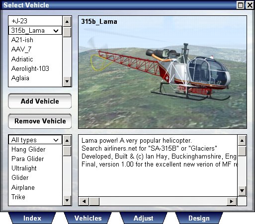
When you select the type from the type box only vehicles of this type will appear on the upper list.
After selecting the vehicle from the list above, the properties of this vehicle will be shown below and its picture will appear above.
Press "Select Vehicle" to select this vehicle as your own vehicle, if you had another vehicle, this vehicle will be added and placed in the same position as the vehicle you had.
This is the dialog that lets you manage the vehicles in the scene, using it you can add vehicles, remove vehicles and adjust some settings for each vehicle.

On the right side of this dialog you see the list of vehicles in scene, on the right side you see a list of available vehicles.
To add a vehicle to the ones in scene, select it from the right side list and press "Add Vehicle", after that you will see this vehicle appear on the left side list.
To remove a vehicle from scene, select it from the left side list and press "Remove Vehicle", it will be removed from the scene and left side list.
If you wish to replace your existing vehicle with one of the available vehicles, select it from the left side list, and press "Select vehicle".
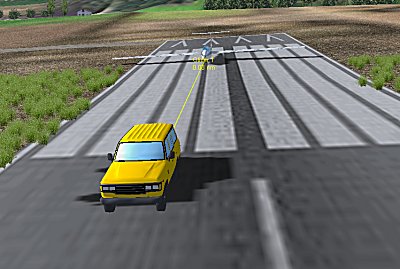
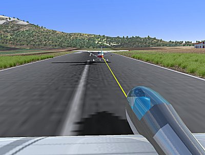
This dialog also lets you tow or be towed, vehicle tows can be ground tows, land tows, or aerial tows.
You can tow your vehicle by a ground vehicle, or by an another airplane, to select towing method, first be inside the vehicle you wish to tow, and then select towing method from the buttons below.
To have another vehicle tow you, you must be in control of one vehicle and then select the towing vehicle from the list on the left side, and press "Tow me", this option is suitable for case where you wish to have the vehicle in front of you tow you.
To have a ground vehicle added and tow your vehicle, you select the option "Ground tow" on the right side of the dialog, this will add a dummy vehicle which only functions as a ground towing point and disappears as soon as you release your tows.
To have a real vehicle be added in front of your vehicle, and tow your vehicle, select the option "Vehicle tow", this will actually add another vehicle at cable length in front of you and set its auto pilot to tow your vehicle.
For each of the three towing options, you have also some paramters you can adjust, these include:
You can select either a cable with fixed force and variable length, or a cable with a fixed length and variable force, the safest method to tow is the fixed force cable, this is the default method used.
To adjust the speed, force or length of cable enter the values you wish into the text boxes below, these values are set by the program according to the weight of the vehicle you select, but you can modify them as needed.
To select a ground tow press "Ground Tow".
To select an aerial tow, be inside the vehicle you tow, and select the towing plane for the right side list, then press "Vehicle Tow".
To release the vehicle you are towing or ones that are towing you, press "Release all tows".
Press the "Vehicle Adjust" button to show the vehicle settings, see details of this screen below.

This screen allows you to adjust quickly some of the vehicle state, here you can enable the auto pilot, turn on the engine, refuel the vehicle, reload weapons and repair a broken or sunken vehicle.
You can also adjust the altitude, heading and speed of any selected vehicle.
Any vehicle can have a replay loaded and saved, replays are available immediately as you fly, or also after the flight is over, provided you have saved the replay for the vehicle you are interested in.
When you are loading a replay, the vehicle for this replay is also loaded, and the replay plays continuousely and functions as a traffic vehicle in the area in which it was recorded.
Any type of vehicle has its own auto pilot with its own functions, for planes the auto pilot screen contains automatic landing and take off as well as the elevation, heading, rate of climb, collision avoidance and navigation.
Press A to show the auto pilot screen, this is the layout for airplanes :

The auto pilot layout is based upon the Bendix/King auto pilot family, the functions of the buttons are:
AP - enables or disables the autopilot functionality.
HDG - enables the heading control, when pressed sets the current heading as the value to maintain, pressing the left and right arrows on the right side of the instrument changes the heading by 10 degress.
NAV - enables waypoint navigation, when active the and waypoints exist, they take precedence over the heading function.
ALT - enables the altitude control, when pressed sets the current altitude as value to maintain, pressing the up and down arrows on the right side of the instrument changes the altitude by 500 ft.
ROC - enables the rate of climb control, when pressed sets the current rate of climb as value to maintain, pressing the up and down arrows on the right changes the rate of climb by 100 ft/min.
COL - avoids collision with land, when imminent collision is detected throttle and steering are used and take precedence over all other functions.
LIFT - this function attempts to find best lift when flying a glider or without engine power.
LAND - this function auto lands the airplane at nearest runway when available.
TO - this functions performs automatic take off, turning on engine, turning off brakes, and establishes a climb untill 500 ft AGL is reached.
Press A to show the auto pilot screen, this is the layout for boats :
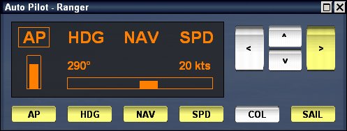
The auto pilot layout is based upon the Bendix/King auto pilot family, the functions of the buttons are:
AP - enables or disables the autopilot functionality.
HDG - enables the heading control, when pressed sets the current heading as the value to maintain, pressing the left and right arrows on the right side of the instrument changes the heading by 10 degress.
NAV - enables waypoint navigation, when active the and waypoints exist, they take precedence over the heading function.
SPD - enables the speed control, when pressed sets the current speed as the value to maintain, pressing the up and down arrows on the right side of the instrument changes the speed by 5 knots.
COL - avoids collision with land, when imminent collision is detected throttle and steering are used and take precedence over all other functions.
SAIL - sets the auto sail function for the sailboats, when enabled sails are adjusted to be optimally oriented to the appearent wind, also when enabled the boat will try to avoid sailing into the wind.
Press the "Replay" button to show the following screen, you can also press F8 to show this screen.
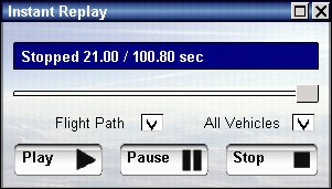
The replay mode, stores up to 5 minutes of vehicle replay, you can scroll through this replay, go back to a moment you wish, and then play it again.
You can also exit the replay at any moment and continue the flight from there, for example, when you practice a difficult maneuver, you can go over and over again to a point in time, and make the maneuver differently, the replay will record every attempt you made and will you them all if you choose.
Replays can also be saved and used as traffic in the same position they were recorded.
To save the replay of your current vehicle, press "Save My Replay".
When you load a replay it also loads the vehicle the replay was recorded on.
The replay dialog also shows the flight path, so you can see the replay path, you can also turn on this path by pressing Shift + P.
When loading a replay, the vehicle loaded will be in a looping replay mode, you can press "Clear My Replay" to turn off this mode.
Press the "View Points" button to show the following screen, you can also press Shift + V to show this screen.
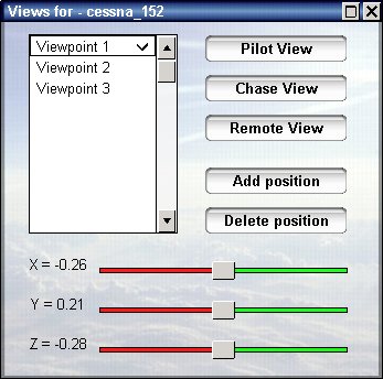
This dialog becomes active once you have a vehicle, then you have the following view options:
Pilot View - sets you at the cockpit, with default point of view for this vehicle.
Chase View - sets the camera in chase view around the vehicle, you can move the camera with the mouse.
Remote View - sets the camera in a stationary position outside the vehicle, you can move the camera with the mouse.
Leave vehicle - releases control of the vehicle and moves the camera outside, you can undo this by pressing Pilot View.
The list on the left side shows you views you have defined and saved, you can select any of them from the list to go quickly to this point, when you are in pilot view you see through this point, when you are in chase view you see around this point.
You can move your point of view with the three sliders, you can move the X, Y, Z coordinates of the view relative to the vehicle's body, you can also move your point of view using the mouse and keyboard.
Once you wish to save your position as a new view press "Add Position", when you wish to delete the last position press "Delete Position", all of these positions are saved in a file called views.cfg inside the vehicle directory.
There is a great similarity between the file views.cfg, lights.cfg and smokes.cfg, all of these files are in the same format and are all relative to the vehicle's body, you can easily measure positions on the vehicle and add views, thus creating a file you can use for other purposes as well.
Press the "Show Scripts" button to show the following screen, you can also press Shift + F8 to show this screen.

In this screen you see for each vehicle in the scene, if a script is loaded and the state of its execution.
A script is a set of commands which operate on a higher level that the vehicle auto pilot, and control the behavior of the vehicle for a specific task and time, for example "takeoff" or "land" are high level script commands that make the vehicle perform a series of operations untill a certain situation is reached.
If your vehicle shows very abrupt response to auto pilot commands, you can adjust the auto pilot gain, using vehicle design mode, a safe value can be 0.5, then save the properties for this vehicle.
For detailed explanation of the script language used see the Script Readme.
The script dialog, can be used to load a script of your choice from the scripts directory of the program, to clear an assigned script and to set the point of execution inside a script.
When you save a situation, the script or replay loaded for each vehicle are saved as well, and function as soon as this situation is reloaded.
Press W to show the weather dialog, this dialog consists of four categories; weather, time, forecast and advanced.
The weather category is for changing current weather and time, selecting it shows the following dialog:
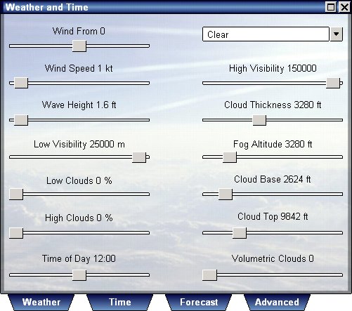
In this dialog you adjust all aspects of weather you can control, this includes sea and atmospheric conditions.
Vehicle Simulator allows you to select three altitudes of primary atmospheric effects, these are the cloud base, the fog altitude and the cloud tops.
The Cloud Base effects the base of the clouds and also the thermal activity, thermals are strongest below the cloud base, and gradually diminish until cloud top is reached.
The Fog Altitude effects the visibility and layered fog effect, it can be set to be equal to cloud base, to form a typical atmosphere, or to lower to form a typical morning fog covering the low valleys.
The Cloud top is used to set the top layer of clouds, typically of type cirrus.
You can have low clouds and high clouds, and control the coverage of both, you can also control the thickness of the lower clouds, which are typically of cumulus type.
Volumetric clouds are visually 3D, and also exhibit atmospheric activity, they can produce updrafts below them and downdrafts around, typically resulting in a doughnut shaped flow.
You can control the amount of thermal activity produced by volumetric clouds by adjusting "Cloud Suck" in the advanced weather dialog.
Selecting the time tab will show the following screen.

This screen will allow you to set time of day and exact date and year, this will set the sun, moon and stars to the exact orientation they have in the sky depending of time and the location you are in.
In addition, you can also control the amount of visible stars for the purpose of navigation and oreintation on the night sky.
Press Set Time To Now to set time in the program to your local time, the position of sun is determined by the time position and date.
Vehicle Simulator calculates the orientation of sun, moon and stars according to standard astronomic calculations, however deviation from reality may occur.
Selecting the forecast tab will show the following screen.
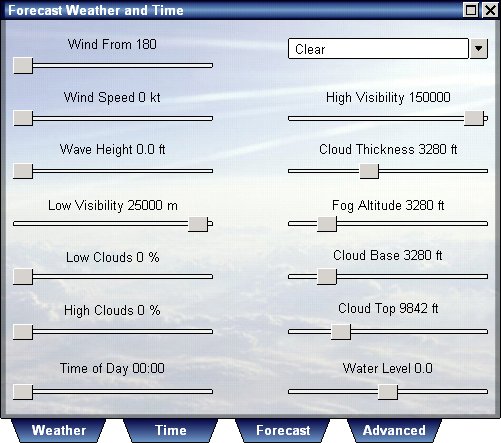
On this dialog you can set the weather conditions to be used at the time specified as forecast time, the weather then changes smoothly between the weather conditions defined on the weather dialog, and the conditions defined on this forecast dialog.
When forecast time is reached, a new forecast is automatically generated and the forecast time is set to 6 hours ahead of currect time.
Weather forecast can be turned off to make your flying or sailing experience predictable and constant, use the advanced weather dialog to enable or disable the weather forecast.
Selecting the advanced tab will show the following screen.
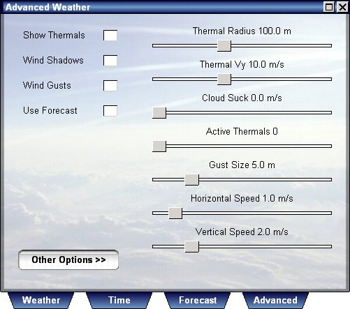
This dialog allows you to control some of the advanced atmospheric features of Vehicle Simulator.
You can control thermals, changing their existence, density, radius, strength and visibility.
You can control vertical gust activity inside clouds, this creates some well known effects such as micro burst and more, and can be very dramatic to fly through.
You can enable wind gusts, and control its frequency, strength, horizontal and vertical components.
You can enable the wind shadows, which are the effects of wind obstruction between boats sailing close to each other, although the effect is active for all types of vehicles, the most common use is for sail boat overtaking tactics.
You can also turn on or off the weather forecast, using the weather forecast makes the weather change between the current weather conditions defined in the weather dialog, and the forecast weather conditions defined in the forecast weather dialog.
Pressing the other options opens the advanced atmospheric options which overlap and complement the advanced weather options.
Vehicle Simulator allows you to add many different types of animals, the program was made to have additional types of animals created as add-ons, and also to have their behavior fully customizable by add-on makers.
Select from the main menu Change Animals to show the animals dialog, or press Shift + A.
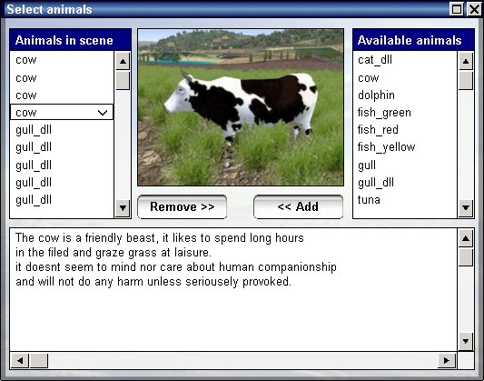
On the left side you will see the list of existing animals in the scene, you can add up to 64 animals of any type to the scene.
On the right side you see a list available types of animals, for each one you select you will see a picture and a short description below.
To add animals select the type you want from the right side list and press "Add", to remove animals select the type you want from the left side list and press "Remove".
Each animal is visible once the observer is close enough to it, if for example, you add shallow water fish they will be visible only at shallow water, for each animal there is also a different behavior, for example, sea gulls will not wish to fly at night or in rain and will head off to shelter.
Animals can be also created by users as add-ons, there can be simple animals and also more elaborate ones defined by a dynamic link library.
Vehicle Simulator supports a global scenery model, this means that whenever your vehicle is inside any scenery boundary the appropriate scenery is loaded for this area.
Scenery boundary extends in 3D as well, if your vehicle is above 80000 ft scenery is unloaded and the global scenery is loaded instead, global navigation is possible inside and outside of scenery borders, and your coordinates are used to determine your position upon the globe.
You can conduct flights inside or outside of atmosphere up earth orbit, once you enter the atmosphere you can land in any scenery you choose.
Sceneries can be made for smaller area inside a larger scenery
area, when the vehicle enters this area the more detailed scenery is loaded.
To disable this option by turn off "scan scenery" in the graphic options
dialog.
To change your position and your scenery, press Change Scenery from the main menu or press "M" to show the map.
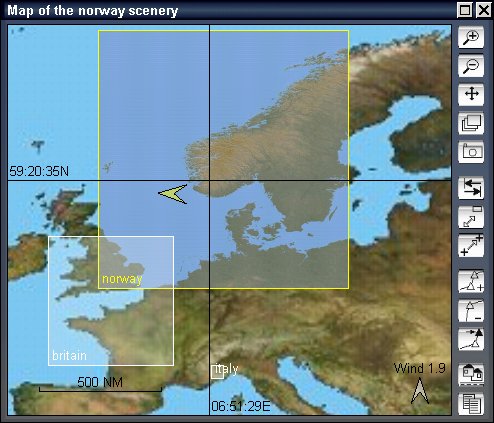
Each of the existing sceneries is shown on the map as a rectangular bright area, and also is seen on the right side list.
You can add more scenery areas by downloading them from the websites of Vehicle Simulator, or by importing digital topographic maps directly.
To select the area of interest, select them from the map, then zoom in until you see the area on the map clearly, and then press "Move to point", this will move your vehicle into this position and scenery.
When several sceneries overlap for the position you selected, the more detailed area will be loaded.
When several sceneries overlap for the position you selected, the more detailed area will be loaded.
However you can control this behavior, for the purpose of using the scenery you desire instead of the scenery the program selects automatically, to disable the automatic scenery selection disable the "Scenery Scan" inside the land options dialog.
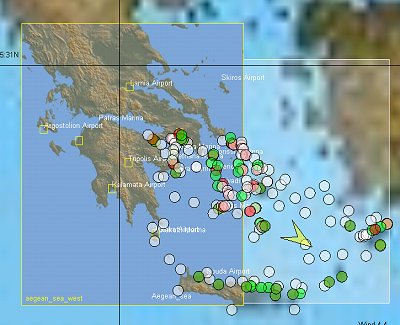
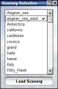
When scenery scan is turned off, you can manually select the scenery to use, using the Change -> Scenery dialog, this allows you to use multiple scneries defined for the area you are in, for example using the Aegean_sea instead of the "Aegean_sea_west", etc..
The most important tool in Vehicle Simulator is the map, learning to operate the map properly is the key to exploiting the full capacity of the program.
Press M to show the map dialog, the map can be marine or aeronautical map, to select the type of map use the "Marine" option at the bottom of the map.
By default the marine map has topographic lines of sea depth, and the aeronautical map has topographic lines of land elevation data.
To see the distribution of objects upon the map press "Objects", the automatic objects are shown in yellow, the user objects are shown in red.
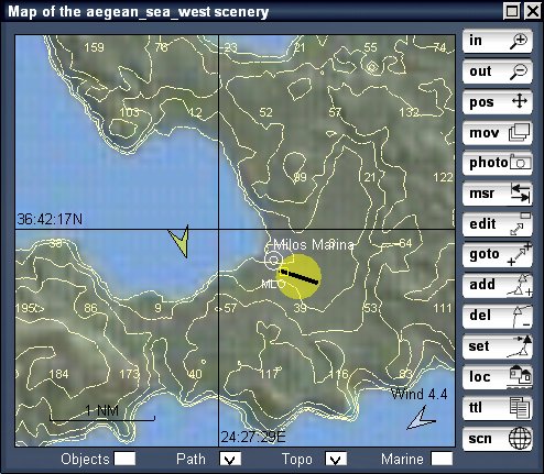
Zoom out until you see the borders of your scenery, part of
the world map, and other scenery areas.
You can create waypoints between these sceneries and navigate to them.
To move quickly between sceneries press the press the Scn icon on the bottom part of the map, then select the scenery of your choise, then press Accept, you will see the selected scenery appear on the map, but not loaded yet, then select your position using the map cursor, and then press "Goto", this loades the selected scenery and moves your view and vehicle to the selected position.
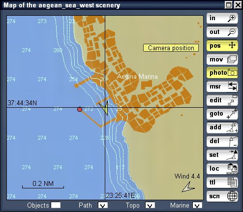
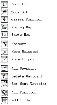
The top two buttons are used for zooming in and out, to move the map simply click on the map and drag it with your mouse, to center your view press the camera position button.

Vehicles and waypoints can be moved on the map, to do so press the "move selected item" button, pick the object and drag it to the new position, press this button again to exit this mode.
You can also move the camera or your vehicle to a desired location, to do so pick on the desired location on the map and then press the "move to point" button, if you were onboard a vehicle the vehicle is moved, if your camera was free only the camera will be moved.
Press the "measure distance" button and then move your mouse around your position, the distance between you and the selected point as well as the azimuth to it will be shown on the map, once done measuring, press this button again to exit this mode.
Any point you pick in measure mode, is also copied to the clipboard, this is particularly useful when designing a scenery, see more on that below.
In Vehicle Simulator you can have up to 64 waypoints, these waypoints are shared between all vehicles in the scene, however you may assign different waypoints to each vehicle, thus creating different routs for each vehicle.
To add a waypoint pick the desired position on the map and click the "add waypoints" button, to remove a waypoint, select it on the map and click the "delete waypoint" button.
To assign a waypoint as the next waypoint for any vehicle you wish, select the vehicle on the map, select the waypoint on the map and press the "set next waypoint" button.
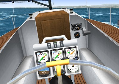
Vehicle Simulator has two types of instrument panels, the ones you see directly on screen, and the ones you see attached to vehicles.
These panels function in the same way, all their instruments and switches work when you manipulate them with your mouse, and the data they show is related to the vehicle you control.
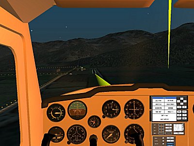
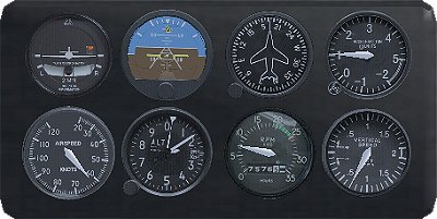
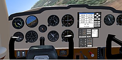
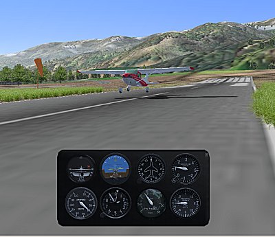
Press P to show the panel, this will show you a panel specific to the vehicle you control, for example the panel for planes looks like this:
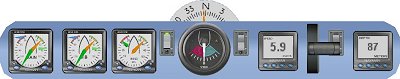
The onboard panel of this type looks like this:
Panels can be used also in tower view of your vehicle, and you can control it from a distance like a radio controlled vehicle.
Any vehicle can show any panel you wish to show, press Control + P to show panel selection dialog.

The head up display or HUD is used to show vital flight information around
your point of view, press H to show the HUD.
The HUD is also used in some instrument panels, and displays the same data as
the onscreen HUD.
These are the types of data displayed on the HUD:
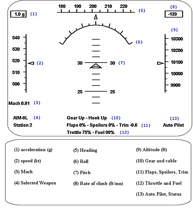
The heading shown on the HUD can be the true heading of the vehicle, or can be the heading of camera view, to select camera heading select "Free View HUD" from the vehicle options dialog.
Any vehicle can be configured to carry weapons, weapon types include; bombs, cannons, rockets, guided missiles and torpedos.
To select a weapon press Shift + Backspace, this will cycle between existing
weapons and show you the selected type in the HUD view.
Weapon will only be selected for vehicles which have a weapons defined.
When a guided missile is selected a diamond shape will appear on the HUD and a lock tone will be heard when another vehicle is in view, this means the weapon is locked on the other vehicle and will intercept it when fired.

Each weapon can be aimed to your point of view, to select a weapon press Shift + Backspace, or use the weapon view of the aerial radar, you can use the Telescope view, or the HUD view as sight to aim your weapon, the HUD also shows lock on status and sound when the weapon is guided and locked upon a target.
When a bomb is selected a square shape will appear under the plane, and a line connecting it to the center of your HUD, this square marks the Continuously Computed Impact Point ( CCIP ), using this point you can plan your bombing more precisely.
To shoot the selected weapon press Backspace, or joystick button 1.
Each vehicle and each scenery object you shoot upon can sustain a certain amount of damage, when hit a simple explosion will be seen, when the damage is larger smoke or fire will be seen as well and vehicle will be broken.
To manage weapons, targets and ranges use the RADAR screen below.
Weapons can limited or unlimited, when weapons are limited their weight is subtracted from the weight of the vehicle when they are shot, and also the quantity diminishes untill no shells are left for this weapon type.
The amount of shells available for each weapon type is shown on the HUD for each weapon selected.
Weapons can be reloaded using Control + Backspace.
Vehicle Simulator contains two types of radars, marine radar and aviation radar.
The AVIATION RADAR is responsible for showing targets around your vehicle, weapon status for your vehicle, and for engaging and firing upon these targets.
Press R to show the following screen:
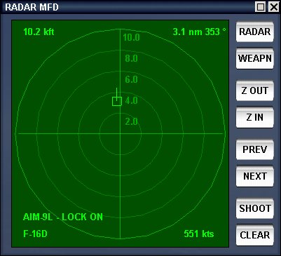
The RADAR instrument has two screens, RADAR and WEAPON, to show either one press the appropriate button on the top.
The two buttons below zoom in or out, any target closer than the maximum distance shown, is drawn as a cross, or as a rectangle when selected.
To select targets and display their data press Next or Prev, when a target is selected the selected weapon will lock upon it, and you will see its data in all four corners of the screen.
To clean a selection or unlock a weapon press Clear, to shoot the locked or selected weapon press Shoot.
Pressing Weapon shows the Weapon screen:
The weapon screen, shows you the available weapons you vehicle has, and also the stations on which they are attached.
The weapon screen has similar functions as the RADAR screen, but the Prev and Next buttons select weapons and not targets.
When a weapon is locked upon a target its status will appear inside the selection rectangle.
The quantity of rounds left for each weapon is shown inside the parenthesis.
The MARINE RADAR is responsible for showing targets around your vehicle, collision prediction for these targets, and elaborate tracking information.
Press Shift + R to show the following screen, this dialog has several modes which are typical to a modern radar instruments.
Adjusting position - to move the map use the four arrows at the top, this also puts the radar in the off center position and you see the "OFF-C" appear on the bottom right of the screen.
The bottom side of the screen shows your position, speed and heading, when the map is in off center mode, the position is the position of the center of the map and not the position of your boat.
To return the map to the center, press the "CTR" button.
Adjusting range - to adjust the range of the radar press the "Z OUT", "Z IN" buttons, you will see the range appear on the top left side of the screen, and the spacing between each ring in nautical miles.
Adjusting zoom - after you press the arrows or the zoom buttons the knob goes into zoom mode, drag the mouse over the knob to control the zoom level, the zoom is shown on the lower right side of the screen.
Selecting modes - the radar map has four modes of display:
North up - the map is pointing north.
Head up - the map is pointing where your ship is heading.
Track up - the map is pointing to the next waypoint.
True motion - the map points up, and the land becomes static, your ship is moving just as it would move on a regular static map.
The selected mode is shown on the top left side of the screen, the white line going from the center of the map, is the heading line, it shows your heading.
Measuring azimuth and distance - the radar can measure azimuth and distance from the center of the map to any point on the map, to do so use the "EBL" and "VRM" buttons.
The "EBL" bottun shows the yellow EBL line on the map, and sets the knob to EBL mode, you can adjust this line using the knob and read the angle on the bottom part of the screen.
The "VRM" button shows the yellow VRM circle on the map, and sets the knob to VRM mode, you can adjust this circle using the knob and read the distance on the bottom part of the screen.
EBL and VRM can be used together to get the exact distance and azimuth to a target.

Acquiring targets - when the radar identifies a moving object as a target this target becomes acquired, you can acquire any boat including your own and see its information displayed on the upper right corner of the screen.
The information displayed is: the name of this boat, the range to this boat, the bearing to this boat, the course it is traveling, the speed it is traveling, the length of track shown, the closest point of approach, the time to closes point of the approach.
When you acquire a target the knob goes to track mode, you can adjust the length of visible track line by adjusting the knob, the track line is shown in green behind the targets, and its length is measured in minutes.
Measuring collisions - When two boats head towards each other and their courses are not parallel their courses will intersect, the boats will become closer and closer until they collide of pass by each other.
The closest distance between the boats is calculated by the radar and is shown on the upper left area as closest point of approach and time to reach this point.
When the closest point between the two boats ( TCPA ) is less than the radius of the two boats combined there will be a collision between these boats, the time to this collision is shown as time to closest point of approach ( TCPA ).
The image above shows such possible collision about to take place in 74 seconds.
Man overboard - when you press the "MOB" button, a yellow rectangle will appear on the map at the same position you are in, this will allow you to return to the same point, your path will also be shown in green.
The GPS is one of the most used instruments in aviation, and navigation in general, press Shift + G to show the GPS.
The GPS has several modes which are typical to a modern GPS with map, the layout used is similar to the one used in various Garmin hand held devices.
Switching between modes is done by pressing the "NAV" button.
The Time screen - this screen shows the time of day, time to go until the next waypoint is reached, estimated time at next, time elapsed since start of navigation, distance to go until next waypoint and total distance passed since start of navigation.
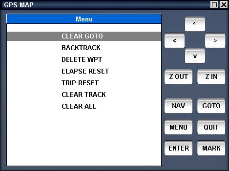
You can reset the trip and the elapsed time using the menu of the GPS.
The position screen - this screen shows your position, speed, elevation, time of day, date, heading, bearing to next waypoint, distance to next waypoint and total distance traveled.

The compass screen - this screen shows your bearing to next waypoint, your distance to next waypoint, your heading and your speed, the rosette shows the compass and the next waypoint relative to you, the needle shows the direction to the waypoint.
The map screen - this screen shows you the map, upon it your position is marked as a black triangle pointing to your heading, the waypoints and route are seen also as they are on the main map of the program.
You can pan in all directions and zoom in and out to see the area of interest on the map.

The goto screen - If you
wish to set your next waypoint press "GOTO" button.
If you wish to set man overboard waypoint, press "GOTO" and then "MOB".
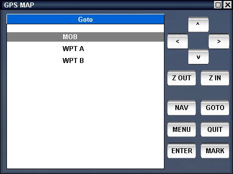
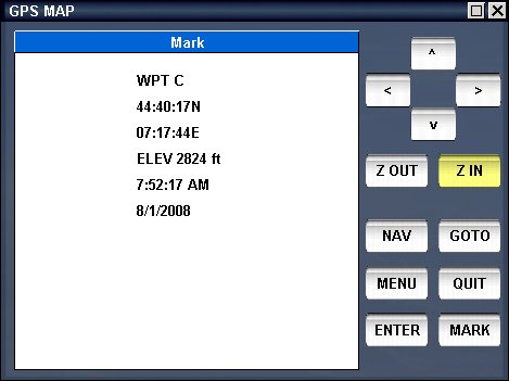
The mark screen - You can mark your position as a new waypoint by pressing "MARK" and "ENTER".
The menu screen - You can also perform other functions using the "MENU" button.
To accept a menu command press "ENTER", to cancel press
"QUIT".
The most challenging flights are made when visibility is poor or when complicated navigation has to be performed, few planes have actual moving maps and GPS displays, but almost all of them have radio navigation instruments which can be used for finding your location and performing accurate approaches and landings in limited visibility.
When you open the map you see radio navigation aids colored in white, these consists of NDB , VOR, ILS beacons.
NDB can be picked up by the ADF or RMI instrument on your plane.
VOR can be picked up by ILS, VOR, NSD, ADI instruments on your plane.
ILS can be picked up by ILS , ADi instruments on your plane.
Selecting these navaids is done using the NAV dialog or by pressing N, the following screen appears:

In this screen you have selection of ADF, NAV1, NAV2 frequencies, and also DME ( distance measuring equipment ) readings for NAV1 and NAV2.
Only appropriate navaids can be selected for each type of navigation instrument you have, selecting a wrong type will result in the frequency showing 000.
Instruments have a limited range for which they are effective, if you select an instrument which is too far, the instrument will show you the red indicator and will not receive the signal from this device.
Each radio or navigation instrument can be adjusted using the mouse only, to adjust an instrument use left mouse drag and pick on the instrument you wish to adjust, then move the mouse up or down.
The following instruments can be adjusted:
Gyro - moving mouse up down will adjust the heading.
ADF - moving mouse up down will adjust the heading.
RMI - moving mouse up down will adjust the heading.
VOR - moving mouse up down will adjust the OBS.
ILS - moving mouse up down will adjust the OBS.
RMI - moving mouse up down will adjust the OBS.
To clear all adjustments and frequency selection use the Reset button.
To visualize radio navigation use the option Show Navaids in the vehicle settings, this shows you the ILS, VOR and NDB as seen in the following picture.
Any type of vehicle has its own auto pilot with its own functions, for planes the auto pilot screen contains automatic landing and take off as well as the elevation, heading, rate of climb, collision avoidance and navigation.
Press A to show the auto pilot screen, this is the layout for airplanes :
The auto pilot layout is based upon the Bendix/King auto pilot family, the functions of the buttons are:
AP - enables or disables the autopilot functionality.
HDG - enables the heading control, when pressed sets the current heading as the value to maintain, pressing the left and right arrows on the right side of the instrument changes the heading by 10 degress.
NAV - enables waypoint navigation, when active the and waypoints exist, they take precedence over the heading function.
ALT - enables the altitude control, when pressed sets the current altitude as value to maintain, pressing the up and down arrows on the right side of the instrument changes the altitude by 500 ft.
ROC - enables the rate of climb control, when pressed sets the current rate of climb as value to maintain, pressing the up and down arrows on the right changes the rate of climb by 100 ft/min.
COL - avoids collision with land, when imminent collision is detected throttle and steering are used and take precedence over all other functions.
LIFT - this function attempts to find best lift when flying a glider or without engine power.
LAND - this function auto lands the airplane at nearest runway when available.
TO - this functions performs automatic take off, turning on engine, turning off brakes, and establishes a climb untill 500 ft AGL is reached.
Press A to show the auto pilot screen, this is the layout for boats :
The auto pilot layout is based upon the Bendix/King auto pilot family, the functions of the buttons are:
AP - enables or disables the autopilot functionality.
HDG - enables the heading control, when pressed sets the current heading as the value to maintain, pressing the left and right arrows on the right side of the instrument changes the heading by 10 degress.
NAV - enables waypoint navigation, when active the and waypoints exist, they take precedence over the heading function.
SPD - enables the speed control, when pressed sets the current speed as the value to maintain, pressing the up and down arrows on the right side of the instrument changes the speed by 5 knots.
COL - avoids collision with land, when imminent collision is detected throttle and steering are used and take precedence over all other functions.
SAIL - sets the auto sail function for the sailboats, when enabled sails are adjusted to be optimally oriented to the appearent wind, also when enabled the boat will try to avoid sailing into the wind.
Vehicle Simulator can connect to other users and let you see their vehicles, interact with them and chat, connection can be done using the internet or LAN.
Several trackers exist to track and show you active network sessions, and more trackers can be easily added using an external file inside the network directory of the program.
Up to 24 user can share each session, each user can have his own vehicle or can be a guest on a vehicle controlled by other users.
Weather conditions, waypoints, vehicle position and actions, and chat messages are passed between all users in the session, any change made to weather, waypoints or vehicles is immediately copied on all machines sharing the session.
The host machine is the first machine to start a session, guest machines are the machines that join in.
Whenever a host quits the game hosting is passed to another user in turn, so that the session continues, however this session will not appear on the tracker any more.
To connect online select Network Connect from the menu, this will show the connection dialog.
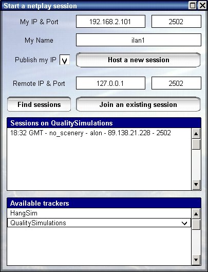
At the top of this dialog you see your IP address and port used, below you can enter your name, this name will be used for the online session as your call sign.
You can host a new session or join an existing one, to host a new session press "Host a new session" and wait until session is established.
You can select "Publish my IP" if you wish others to see your session on the internet and join you.
To see other sessions currently active press "Find sessions", you will see a list of sessions below, the time they were started ( given in GMT ), the scenery they are at and the name of player hosting this session.
To join any of these sessions select it from the list below and press "Join an existing session".
Alternatively, if you know the IP address or name of computer you wish to join, type this address at the remote IP textbox and press "Join an existing session".
Names can be resolved without the use of specific IP addresses, if you are on a LAN you can enter the name of the machine instead of its IP address.
Once session was established this dialog will disappear and you will see a message "session has started".
The chat mode - the chat mode is much more than just a tool for chatting, it can be used when you are not playing online as well.
The chat mode is activated by pressing F12, this will show the chat dialog and also a list of chat messages made by players in the session.
Type in your message and press Enter to send it, if you press Escape the message is discarded.
Each player that joins the game is seen as avatar on the right side of the screen in chat mode, you can customize your avatar by changing the me.jpg image inside the network directory of the program.
Your avatar is sent to others players and appears by your name.

The passenger mode - by default each vehicle is controlled by a single player, and seen as such on other players machine, however you can join as a paseenger on any vehicle controlled by another user, and chat with this user as you sail along, in such case you will see a messge appear "controlled by [user name]" on the top mid part of the screeen.
Creating a new scenery
Any scenery in Vehicle Simulator is based upon a digital elevation matrix of the selected area.
This area can be obtained by downloading DEM or SRTM data from
the internet and saved using a program called 3DEM
http://www.hangsim.com/3dem/
To download 3DEM and topographic data see this website
http://www.hangsim.com/3dem/
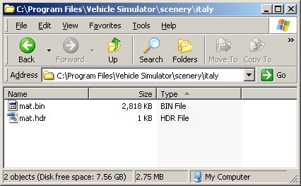
The matrix should be exported from 3DEM using "Save Terrain
Matrix" and selecting "Binary Signed Integer" as the format.
This creates two files [something].bin and [something].hdr, these two files
should be placed into an empty directory inside the scenery directory of the
program.
Start the program and move into this scenery by selecting "Move To Point" from the map view, this will place you inside the scenery and you will be able to design and customize it.
Each scenery is composed of a number of textures, up to eight different textures can be used.
Each texture is placed on the scenery by a set of rules which can be customized, the result can be very elaborate and forms a non repeating pattern that resembles a realistic photographic texture.
Select Design Textures from the main menu, the following screen will appear:

Here you can see the textures that comprise the scenery, each scenery is applied when a set of conditions is met, if conditions are not met the following texture in the list is checked until one is found, these conditions are:
The elevation is given in meters and is the elevation of each point on the ground.
The slope is given in radians, and is measured as the change of elevation divided by change of position along the ground.
The probability is a number between 0 and 1 when 1 mean that every time
conditions are met this texture is applied, and 0 means that even is conditions
are met this texture is never applied.
Probability can be used to avoid repeating patterns when ground is very flat or
very regular in shape.
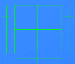
You can edit these conditions changing the elevation and slope and pressing "Apply Changes" to see the result, when changing elevation you will see a yellow grid showing you the elevation you selected visually, for example here is the selection of forest texture:
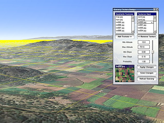
On the left side you can see a list of available textures, these textures are placed inside the "graphics" directory of the program and you can place there any texture you want in jpg format.
To add a texture to the list of textures used, select the texture from the left side and press "Add Texture", to remove a texture select it from the right side and press "Remove texture".
When creating snow that require cliffs show through, always place the snow before the cliffs and let its maximum slope be small ( 0.2 for example ) so that cliffs will be applied if slope is bigger than the snow.
When you are happy with the result you can press "Save Changes", if you wish to cancel the changes you can press "Reload Scenery".
The result of your work is saved inside a file called "scenery.txt" which also includes vegetation information for the textures you have placed, see below more on customizing vegetation.
By default scenery can be changed, however scenery can be copyright protected, if you wish to protect your scenery edit the scenery.txt ( see notes inside )
Each texture you use, can have a dense texture associated, this dense texture
is shown when the camera gets near the ground, and has similar name to the
texture used with the addition of "dense", for example txt000.jpg has
"dense_txt000.jpg" as a dense texture.
When no dense file is found the default "dense.jpg" file is used
instead.
Each scenery can have up to 64 types of vegetation, each type has specific width, height, size and number of elements which appear when camera is close to the ground.
Each type can be shown upon any ground texture you choose, combinations of vegetation types can be used to create forests with grass for example.
Select Design Vegetation from the main menu, the following screen will appear:
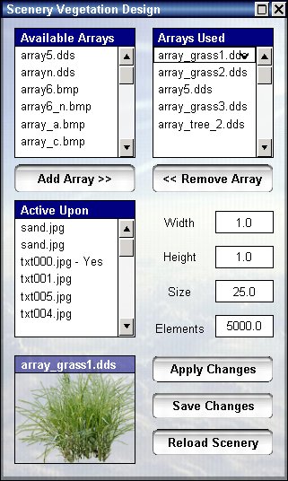
On the left side you can see a list of available textures, these textures are placed inside the "common" directory of the program and you can place there any texture you want in JPG, BMP or DDS format.
To add an array to the list of textures used, select the texture from the left side and press "Add Texture", to remove a texture select it from the right side and press "Remove texture".
For each array you select its width ( width of single element ), height ( height of single element ), size ( maximal distance from camera ) and number of elements.
Each array can exist upon on or more of the ground textures in the scenery, to select which textures to show upon, select them on the lower list on the left.
You can edit these conditions changing the properties and pressing "Apply Changes" to see the result, for example here is the selection of forest with grass:
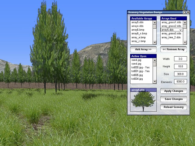
The result of your work is saved inside a file called "scenery.txt" which also includes texture information for the textures you have placed, see above more on customizing textures.
By default arrays are inactive underwater, if you wish to set an array active underwater edit the scenery.txt ( see notes inside )
You can create and place individual objects wherever you wish in the scenery, these objects are loaded when closer than object visibility distance, defined in land settings above.
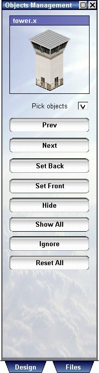
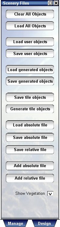
Select Design Objects from the main menu, this will show one of the three design screens, these screens are then accessed using the tabs below them.
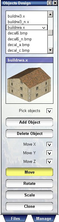
The Object Design screen on the left, is responsible for adding and customizing objects, to add an object select it from the upper list and then look at the point you wish to add it, a yellow crosshair marks the point this object will be added, these press "Add Object".
This object is then selected, and you can move it or change its size and other dimensions, to move in all dimensions allow the three checkboxes to be selected, to move in a single dimension allow only one of them to be selected, for example having moved an object in X,Y,Z you wish to raise it above the ground, select the Y only, and then drag it it.
Scaling and rotation may be used to change other properties as well, in that case the name of property will appear instead of X,Y,Z and you can see the value change as you drag the mouse.
Each object type can have different properties set, for example ordinary objects can have scale, roads can have width, length, curve and angle, arrays can have width, height, elements and area, etc...
Objects have many types and sometimes a different day and night appearance, see the website for more information about this.
To delete an object select it by picking visually on it, and then press "Delete Object".
Multiple objects can be selected by using Shift + Mouse move +
left mouse button to select a window of objects.
Any operation made on a single object can be made for multiple objects.
Multiple objects can also saved when selected using "save absolute
file" or "save relative file".
Selecting specific objects can be tricky sometimes, especially if objects appear one on top of the other, as buildings upon a surface, or individual trees among building etc..
Use the object management screen for this purpose, using this screen you can pick individual objects, hide or show them, add them to a list of ignored objects or reset them to normal status.
When surfaces are created, you can also select which surface or object to draw first and which to draw last, using the Set Front and Set Back, this allows you to have complicated surfaces with objects and other surfaces upon them.
To modify an object select it by picking upon it, and then change its properties using the management screen.
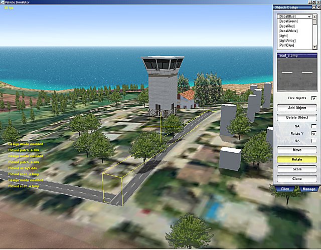
Vehicle simulator scenery consists of two types of objects, objects which
were made by the user on specific positions, and objects that are generated by
the program.
You can create and customize these two types of objects using the Scenery
Files screen.
User Objects
Create some objects with the object design screen, then open the Scenery Files screen and press "Save User Objects", this saves the objects you have made into a file called "objects.txt" inside the scenery directory, this file contains a list of objects to be added on a specific position.
If you wish to duplicate your objects, or use them as a group, press "Save Relative File" and select a name for this group of objects, for example "misc_objects", this will save your objects relative to the camera position.
Now, you can add groups of this type in any location you wish, to do so press "Add Relative File" and select the "misc_objects" you have created, this group of objects will be added at the new camera position.
This procedure can be used to create villages, and towns, these groups are not movable once added, only individual objects in them can be changed.
You can also design the scenery in pieces, adding one part at a time, for this you can create objects and save them with "Save Absolute File", this saves the objects you made in their original positions, and you can later integrate all the groups you have made by pressing "Add Absolute File".
Your goal should be to design scenery in groups and pieces and integrate it at the end, so that the objects.txt file will contain the groups only, and each group will contain the details.
Generated Objects
Each texture you used for the ground can have objects associated with it, these objects will appear on places relative to this texture, for example if you used a texture with farms and forests, you can actually define farms and forests the appear on them.
These objects are generated whenever the texture is used, and therefore are called generated objects, you can select which of these to keep in case you need to customize some areas of the scenery.
To create generated objects for a specific texture, clear all objects first,
then position your camera above the texture you wish to work upon.
Then using the object design form, add objects exactly where they should be
drawn on the selected texture, for example add farms and trees like this:
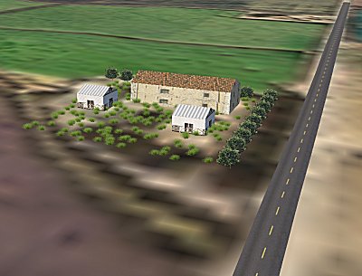
Then press "Save Tile Objects" and this will create a text file with the same name as your texture.
You can repeat this process for other textures as well, and create each file for each texture, when happy with these files, press "Generate Tile Objects" and this will create the file called "auto_objects.txt".
Press "Load Generated Objects" to see objects generated in this file, note that each group of objects is now repeated whenever this texture appears.
You can customize the generated objects by deleting the ones you do not need and then press "Save Generated Objects".
Ground textures and vegetation textures are stored inside the
graphics directory, model files and associated textures are stored inside the
common directory.
The graphics directory is used to store textures and files used by the program
itself, while the common directory is used to store files that are used by one
or more sceneries.
Each scenery itself may contain these files, but they will not be shared with
other sceneries.
See more information and tutorials about scenery design on the website of Vehicle Simulator.
Adding more vehicles
Adding vehicles can be very simple, all vehicles made for Vehicle Simulator, Micro Flight or Virtual Sailor can be added quickly and without trouble to Vehicle Simulator.
To install add-on vehicles use the following procedure:
Download the vehicles of your choice from these
websites:
http://www.hangsim.com/vsf/planes.php
http://www.qualitysimulations.com/vsf/planes.php
http://library.qualitysimulations.com/library.php
Put the add-on file inside your Vehicle
simulator directory which is typically
C:\Program Files\Vehicle Simulator
Run the add-on file there and let it extract itself.
Run the program and let it complete the import of the new vehicle.
See this page for more information about installing add-ons: http://www.hangsim.com/vsf/howto.php
Organizing the Vehicle Files:
Unlike Virtual Sailor and Micro Flight, Vehicle Simulator can have vehicles organized completely inside a single directory, so for advanced users it is recommended to organize the vehicle so that its panels, instruments and weapons are all inside the vehicle directory.
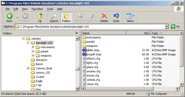
Description of the Vehicle Structure :
The following section gives basic reference and description of the vehicles of Vehicle Simulator.
Detailed description of vehicle making can be found on http://www.hangsim.com/vsf/plane.php
Each vehicle exists inside its own directory under the vehicles directory of the program, inside this directory there are several files that define the structure of the vehicle.
The vehicle configuration file - vehicle.cfg
This file contains the properties of the vehicle, this file can be edited using the properties dialog inside the program, or using a text editor, the file can contain one or more of the vehicle parameters in any order you wish to have, the full list of parameters allowed in this file is given in the table below:
| [type] - type of vehicle hang_glider - hang glider para_glider - para glider ultra_light - ultra light ( light plane ) glider - glider ( plane without engine ) airplane - airplane ( fixed wing airplanes ) trike - microlight ( powered hang glider mounted on wheels ) paraplane - paraplane ( powered paraglider mounted on wheels ) autogyro - auto gyro ( free rotatiing rotor with after propeller ) helicopter - helicopter ( powered main rotor with tail rotor ) automobile - car or land vehicle boat - boat ( powered boat without sails ) submarine - submarine ( submersible without sails ) balloon - hot air balloons and dirigibles [mass] - mass of vehicle (kg) [crew_mass] - mass of boat crew (kg ) moves with point of view and effects boats weight and balance. [has_catamaran] - boat is catamaran or not ( 1 or 0 ) [pilot_name] - name of animated pilot to use [eject_name] - name of ejection parachute to use [wing_sur] - wing area (m^2) [wing_span] - wing span (m) [wing_dihedral] - wing dihedral angle (rd) [wing_height] - wing height above cg (m) - [hang glider, trike] [wing_al0] - wing install angle (rd) [wing_alm] - wing stall angle (rd) [wing_cla] - wing lift line slope (cl/rd) [wing_cd0] - wing zero incidence drag coefficient [wing_cdi] - wing induced drag coefficient [cd_flaps] - added drag coefficient with flaps fully extended [al_flaps] - added AOA with flaps fully extended [cd_spoilers] - added drag coefficient with spoilers fully extended [al_spoilers] - added AOA with spoilers fully extended [cd_gear] - added drag coefficient with gear fully extended [body_area] - body cross section area (m^2) - [gyro, helicopter, car, boat] [body_cd] - body drag coefficient - [gyro, helicopter, car, boat] [cockpit_size] - size of shadow area around cockpit (m) [scale_factor] - scale factor - use 0.3048 to convert model from ft to m [auto_pilot_gain] - auto pilot gain factor of control ( 0 to 1 ) to reduce turn rates use smaller values. [boat_length] - boat waterline length (m) [boat_alt] - boat draft, height of waterline above keel, (m) [boat_cgy] - height of boat CG above waterline (m) [hydro_cruise] - cruise speed of boat with hydrofoils (kt) use 0 for
boats without hydrofoils. [clmax_sailb] - maximum lift coefficient allowed for main sail of
boat ( 0 - 5 ) for square rigger use small values. [has_sails] - boat has sails or not (1 or 0) [sur_sailb] - area of main sail of boat (m^2)
[max_g] - maximum g load (g) [doors_angle] - angle of swing doors rotation (rd) [thrust_angle] - angle of thrust vectoring for boats with outboard
engines ( attach_props = 1) |
The vehicle mesh file - vehicle.x
This file contains the 3D model of the vehicle itself, including its moving parts, any moving part you wish to have, should be named according to the following list of tags, the parts should have their axes defined according to actual rotation axis for this part.
The program seeks also other names of files for compatibility, possible names are plane.x, boats.x, body.x.
The program supports also one optional LOD file which is used when the vehicle is far from the observer, this file is called simple.x.
The program supports also one optional DAMAGE file which is used when the vehicle is broken, this file is called broken.x.
The program supports also one optional LIGHTS file which is used for glowing parts at night, this file is called lights.x.
The program supports also one optional ANIMATED file which is used for animated parts, this file is called anim.x.
The program supports also one optional GEAR file which is used for landing gear, this file is called gear.x.
For paragliders only the program loads also an animated mesh file called wing.x.
The vehicle mesh files are searched for moving parts, part names are identified accoring to name tags, each name is asscociated with a moving part and a specific function, the following table shows the possible name tags and their functions.
elevatorl - left elevator elevatorr - right elevator elevatorm - middle elevator elevatort - rear elevator rudderl - left rudder rudderr - right rudder rudderm - middle rudder ruddert - rear rudder aileronl - left aileron aileronr - right aileron ailerontl - left aileron ailerontr - right aileron elevonl - left elevon elevonr - right elevon stickl - left stick stickr - right stick wheell - left control wheel wheelr - right control wheel stwheel - left boat steering wheel stwheer - right boat steering wheel spropl - left prop spropr - right prop fpropl - fast left prop fpropr - fast right prop srotorl - left main rotor frotorl - fast left rotor strotorl - left tail rotor ftrotorl - fast left tail rotor srotor - main rotor frotor - fast main rotor
srotorr - right main rotor
strotor - tail rotor
strotorr - right tail rotor
strotorl - left tail rotor
pedalr - right pedal
pedaltr - right pedal thrott - trottle handle
spoill - left spoiler
spoiltl - left spoiler sproptr - tip right prop
vtaill - left V tail |
Additional files inside the vehicle directory are optional and include the following files:
effects.cfg - this file defines effects applied on parts inside the vehicle mesh and attached weapons, even line contains a partial name to be searched in the mesh, and reflection and bump scale to be applied on this part.
lights.cfg - this file defines the position and type of lights attached to the vehicle, these include the navigation lights, landing lights and other types you wish to have.
smokes.cfg - this file defines the position, size and color of smoke source attached to the vehicle, these smoke sources emit smoke according to throttle settings.
views.cfg - this file defines the positions of camera views inside the vehicle, these views can be selected, defined and saved using the views dialog inside the program.
elements.cfg - this file defines the positions and properties of simulation elements that compose the vehicle, when this file exists its properties override the properties found in the vehicle configuration file, the elements file can be created, edited and saved using the elements dialog inside the program.
components.cfg - this file defines the positions and properties of components that compose the vehicle, when this file exists its properties override the properties found in the vehicle configuration file and those found in the elements file, the components file can be created, edited and saved using the components dialog inside the program.
smokes.cfg - this file defines the position, color and size of smoke sources emitted from the vehicle.
trails.cfg - this file defines the position and size of smoke trails emitted from the vehicle when flying in foggy areas.
Any vehicle not having elements or components exposes its properties for editing, to edit vehicle properties select the vehicle, and then press the Design tab in the vehicle dialog, the following dialog will appear on the right side of the screen.
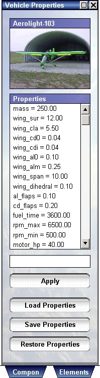 |
On the top part of the dialog appears the selected
vehicle, below appears a list of its properties.
To edit each property select it from the list box and then edit the value in the text box below, click Apply to change the property. Any property can be edited while vehicle is in flight and the result is felt immediately, this can be used to fine tune the dynamic characteristics of your vehicle and to give you important engineering insight about the effect of this property. To revert to saved properties press Load Properties. To save your work press Save Properties. To revert to original properties for this vehicle press Restore Properties. The changes you make are saved at the end of vehicle configuration file, when you restore the properties you delete these values from the file.
|
Any vehicle is composed of elements, these include:

These elements are created by default for any type of vehicle, but are not exposed or editable until you save them for the first time from the elements dialog.
Any vehicle without components defined can have editable elements, elements can be created using the elements dialog and pressing Save Elements.
Press the Elements tab to edit elements, the following dialog will appear on the right side of the screen.
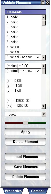 |
On the top part of the screen appears the list of
elements for the selected vehicle, any element has properties which you
can edit and position you can change.
Any element can have a control associated with it, for example a wing can have aileron, elevator, rudder, flap, and more. This control is taken from joystick, keyboard or mouse and functions as it does for standard vehicles. To edit element property select the element from the top list, then select the property from the lower list, then change the value and press Apply. Changing the x,y,z will move the element, and you will see it visually moved on the vehicle itself. The slider helps you move the element or orient it in yaw, pitch and roll. When you select some properties such as control and type a combo box appears instead of the edit text and allows you to select the type. Elements can be added and deleted at will, and also changed in-flight, this can be used to create a precise representation of your vehicle and to give you insight about the function and purpose of each part of the vehicle. To add a new element scroll down on the top list to find a list of [new element] types, select the type you wish to add and press Apply, then edit its position and properties using the lower list and test box. Press Save Elements to create editable elements for vehicle without elements, or to save your work. Press Load Elements to load elements file, and undo your changes. Press Delete Elements to delete the elements file and switch to standard vehicle type.
|
Editing the body element
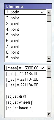 |
When you select the body element of the vehicle you
can change the mass and inertia of the entire vehicle.
You can also change the buoyancy and flexibility of the wheels of the vehicle, instead of changing point by point and wheel by wheel. To change the properties of the entire vehicle select the mass first, set it to desired value and press Apply. Select the [adjust inertia] and press Apply, this will calculate the inertia of the vehicle based upon its dimensions and mass. For planes press [adjust wheels], then press Apply, this will adjust tension on all wheels at once. For boats press [adjust draft], then enter the value for the desired draft of the boat into the text box below and press Apply, this will adjust the buoyancy for all points of boat at once.
|
Simulation elements are responsible for the forces acting upon the vehicle, and for control inputs upon it, but they do not have physical appearance because they are defined in addition to an existing vehicle shape.

The most intuitive concept in vehicle design is vehicle components, these are physical mesh parts with elements attached, these are defined inside the components directory of the program and consist of three files for each component name:
Vehicle with components does not load the default vehicle mesh file, it requires only vehicle configuration and components file to define the vehicle type and shape.
Press the Components tab to edit components, the following dialog will appear on the right side of the screen.
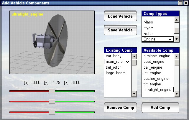
It is recommended to add the body component first as the other components are attached to it, but in case you need to replace the body this component can be deleted and added again.
The body component includes also the panel, camera and pilot data typical for this body, selecting this body will select also its panel and pilot and position your default point of view.
To add a new component select the component type then the actual component and press Add Component.
To delete a component select the component and press Delete Component.
Components can be added, deleted and changed in flight to see their effect on the vehicle behavior.
To change the position of components select the component from the top list, select the x,y,z position and move the slider to move the component in that direction.
To save your work press Save Vehicle.
New components can be made and put inside the components directory, allowing the user to create his own vehicles using interesting combinations of existing parts.
The most impressive feature of Vehicle Simulator is its ability to create a prototype vehicle, this is made possible using vehicle components and the design mode built into the program, allowing the components to be quickly assembled and edited on the fly.
You can change the compoenents position, and and remove components and see the effect it has on vehicle daynamics, this makes the program an unparalleled educational and engineering tool.
To create a new vehicle, make sure no vehicle is selected, if you have a
vehicle selected remove it from scene before you proceed.
Select the vehicle dialog using Change - Vehicle or
press V, then press on the Design tab to show the vehicle design dialog.

On this dialog, you select first the type of vehicle to create and select its body first, for example let's create a flying car.
Selecting "Automobile" as the type, and then "Car_body" as the body type, then press next.
Now we see the new vehicle from the outside, and also the components editing dialog.
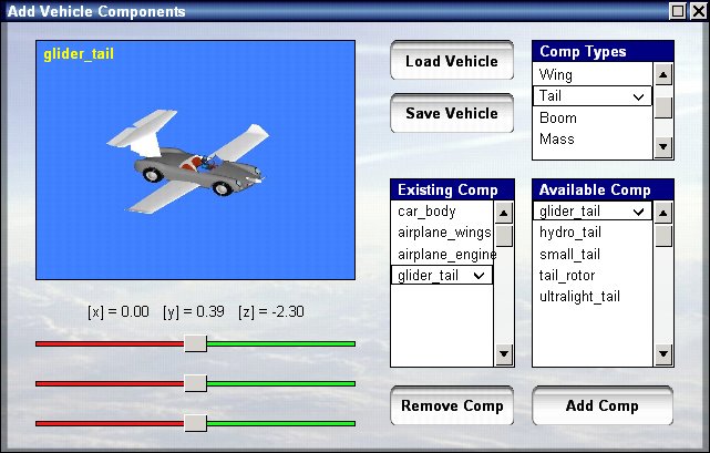
Selecting the wing type, we add airplane wings and press Add Comp, this will add the wings components, and we can change the position of this component using the x, y, z sliders on the left side of this dialog.
After adding also an airplane engine, and a glider tail, we press "Save Vehicle" to save our completed creation, the new vehicle is always saved under the name "new_vehicle", if we are happy with this vehicle we can raname this directory later to any name we want, for example rename the "new_vehicle" to "flying_porche.
Note: Legal vehicle name must not include space inside it, use undescore instead, "new_vehicle" is ok "new vehicle" is not.
Now we are ready for the flight testing, press Escape to close this dialog, and press E to start the engine, B to release brakes, then set full throttle and let the car take off, pulling slightly on the control column.

Our Vehicle is can be accessed and edited using the "New_vehicle" from the vehicle selection dialog.
Multiple combinations can be created and tested, with great joy of experimentation, for example selecting our vehicle we can press the design tab, and get directly to the components editing dialog.
Then we can remove the engine, wings and tail, and add helicopter rotors instead, or a boat engine and and surfaces, and whatever our imagination can create, after each change, do not forget to save the vehicle or the last changes will not be saved.
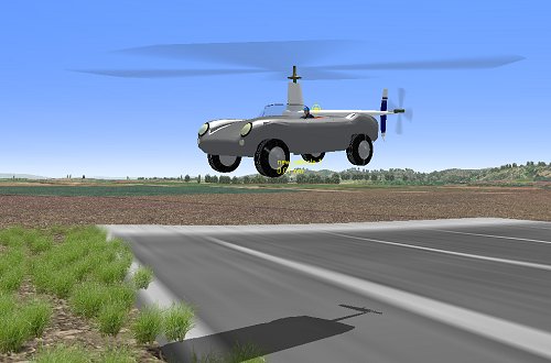
Vehicle Simulator has
several websites from which you can download more vehicles and scenery, and also get
more information about creating these add-ons.
www.hangsim.com/vsf
www.qualitysimulations.com/vsf
There is also a support forum in which you can ask questions and get answers
about using the program or creating new content for it
www.hangsim.com/forums
In case you need help installing or using your program and cannot find
the answers on this document or the websites above please contact support
support@hangsim.com
We wish you a very enjoyable use of Vehicle Simulator and many hours of exploration and fun.
Ilan Papini Tuesday, July 20, 2010